
Mechanical mounting and detaching tool and mounting and detaching method with same

A disassembly tool and mechanical technology, which is applied in the installation and disassembly field of installation tools and track fasteners, can solve the problems of unstable pressure, failure to maintain pressure, and reduce the service life of the hydraulic system, so as to increase the service life and avoid insufficient clamping force. Stabilize and improve the effect of stability

Pending Publication Date: 2019-03-05
洛阳双瑞橡塑科技有限公司
View PDF1 Cites 0 Cited by
  • Summary
  • Abstract
  • Description
  • Claims
  • Application Information

AI Technical Summary

Problems solved by technology

However, the hydraulic floating rail installation tool has unstable pressure during use and cannot maintain the pressure. In addition, frequent pressurization and pressure release during construction accelerates the damage of the hydraulic system and seriously reduces the service life of the hydraulic system.

Method used


Image

  • Mechanical mounting and detaching tool and mounting and detaching method with same
  • Mechanical mounting and detaching tool and mounting and detaching method with same
  • Mechanical mounting and detaching tool and mounting and detaching method with same

Examples


Embodiment 1

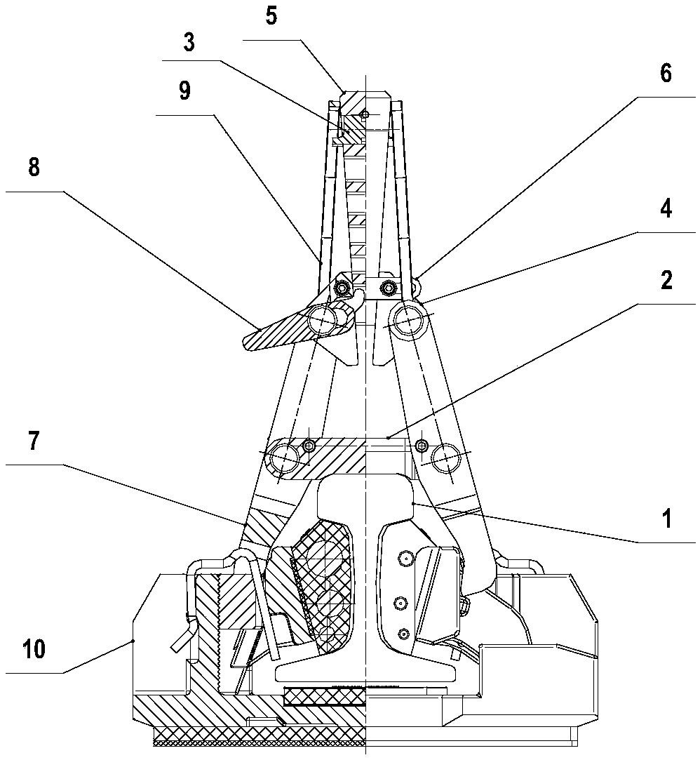
[0038] Such as figure 1 As shown, the present invention discloses a mechanical installation and disassembly tool, which includes two forks 7, and a spreading device is arranged at the upper ends of the two forks 7, and the spreading device can connect the forks 7 and the forks under the action of external force. The floating rail fastener 10 is tightly attached or separated, and then the floating rail fastener 10 is installed or disassembled.

[0039] Preferably, a connecting frame 2 is arranged between the two clamping forks 7 , the two ends of the connecting frame 2 are hingedly connected with the clamping forks 7 , and the lower part of the clamping forks 7 is arranged in cooperation with the floating rail fastener 10 .

[0040] Preferably, the spreading device includes a slanting block 4 arranged on the upper end of the fork 7, the slanting block 4 is hingedly fixed to the fork 7, and a limiting rod 6 is set between the two slanting blocks 4, so that Both ends of the limi...

Embodiment 2

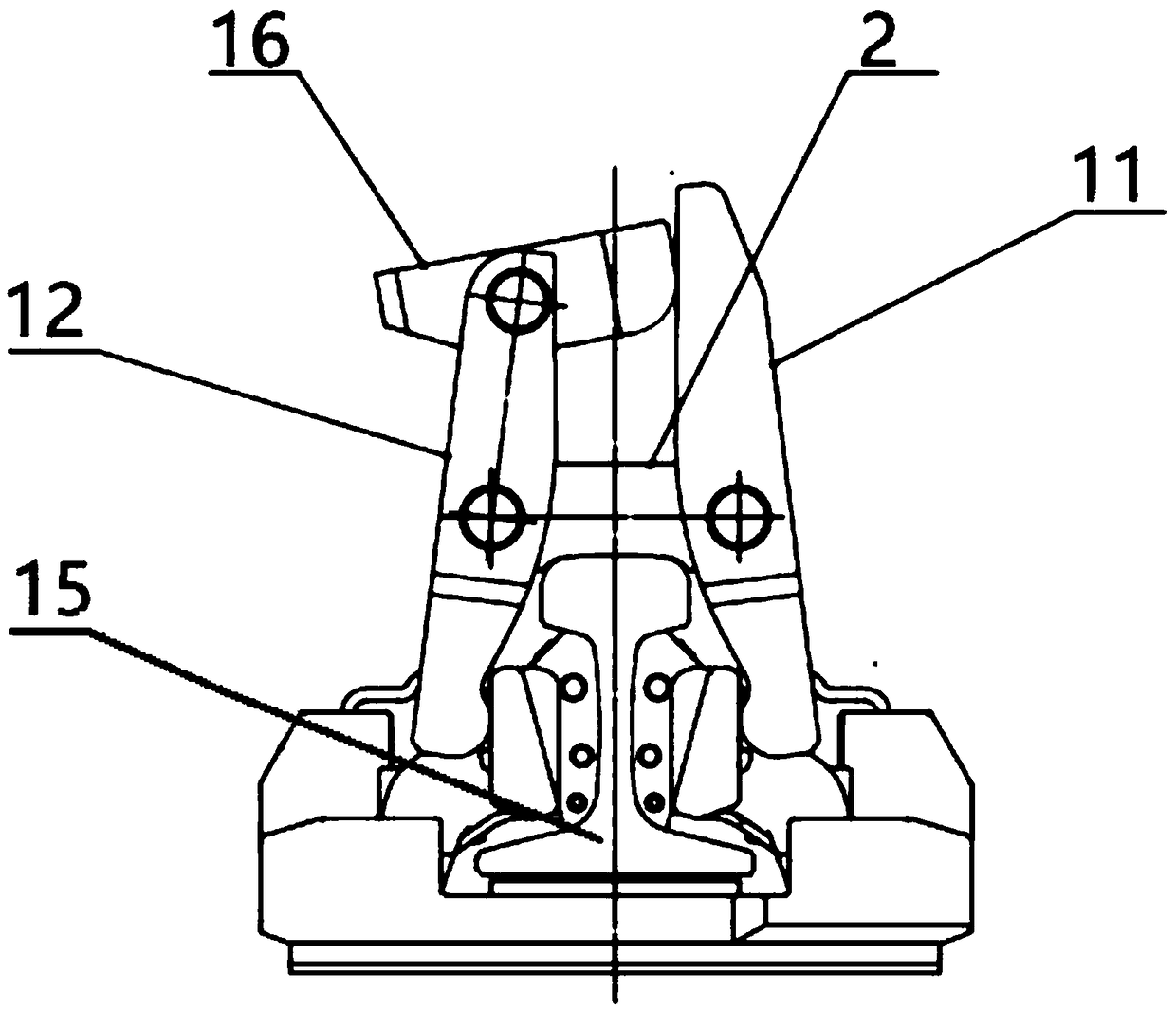
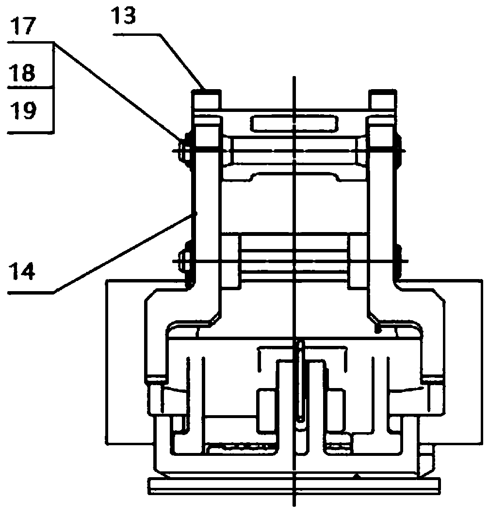
[0063] Such as Figure 2-4 As shown, the mechanical installation and removal tool of the present invention includes a brace device, and a first connecting rod 17 is arranged between the brace devices, and the brace device includes a first brace 11, a second brace 12 , the third strut 13 and the fourth strut 14, the first strut 11, the second strut 12, the third strut 13 and the fourth strut 14 pass through the second connecting rod 18, the third connecting rod 19 Two clamping forks 7 are formed, the lower part of the clamping forks 7 is set in cooperation with the floating rail fastener 10, and a spreading device is arranged on the upper ends of the two clamping forks 7, and the spreading device can connect the clamping forks 7 and the floating rail under the action of external force. The rail fastener 10 is attached or separated.

[0064] As an example of the present invention, the described stretching device is a hammer support block 16, the hammer support block 16 is arran...


PUM


Abstract

The invention provides a mechanical mounting and detaching tool and a mounting and detaching method with same. Diagonal bracing blocks are arranged at the upper ends of clamping forks; the two diagonal bracing blocks are connected with each other through a limiting rod; under the action of a double-position wedge block, the diagonal bracing blocks drive the clamping forks to extrude a floating rail fastener so as to fix or detach a locating wedge block; and therefore, the floating rail fastener is mounted on a steel rail in position or detached. According to the mechanical mounting and detaching tool, stable loading can be realized, the tool is convenient to mount and detach the fastener, the staff efficiency is enhanced, a stable clamping force can be provided, and the floating rail fastener can clamp the steel rail; on the other aspect, a state that the clamping force of a hydraulic system is unstable in also avoided, the stability of the tool is enhanced, and the service life of thetool is prolonged.

Description

technical field [0001] The invention relates to the technical field of installation tools, in particular to the technical field of installation and disassembly of rail fasteners, and in particular to a mechanical installation and disassembly tool and an installation and disassembly method thereof. Background technique [0002] In recent years, with the rapid development of urban rail transit systems represented by subways and intercity railways, the tension in urban traffic has been eased. caused great trouble. [0003] Floating rail fastener is a new type of vibration and noise reduction rail fastener system. The fastener system uses elastic wedge support to support the lower jaw of the rail head, so that the bottom of the rail is separated from the bearing seat, and the rubber elastic block used as an elastic support Then it is supported and positioned by the side panel fixed on the foundation under the rail. Each fastener node of the floating rail fastener system is sup...

Claims


Application Information

Patent Timeline
IPC IPC(8): E01B29/00
CPCE01B29/00
Inventor 陈林赵晓钢段勇奇王彦飞
Owner 洛阳双瑞橡塑科技有限公司
Learn More