Bandwidth scheduling method and device

A scheduling method and bandwidth technology, applied in the field of communication, can solve problems such as increasing the delay of uplink data transmission

Active Publication Date: 2019-03-05
HUAWEI TECH CO LTD
View PDF5 Cites 3 Cited by
  • Summary
  • Abstract
  • Description
  • Claims
  • Application Information

AI Technical Summary

Problems solved by technology

In the process of the above CM sending uplink data, it needs to go through two dynamic bandwidth allocation (DBA) and multiple communication interactions, which increases the transmission delay of uplink data

Method used


Image

  • Bandwidth scheduling method and device
  • Bandwidth scheduling method and device
  • Bandwidth scheduling method and device

Examples


Embodiment 1

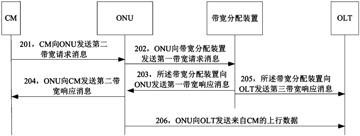
[0076] FIG. 2(a) is a flow chart of the bandwidth scheduling method provided in Embodiment 1 of the present application. In this embodiment, the user-side device is a CM, the first access device is an OLT, and the message conversion device is set on a second access device, and the second access device is an ONU. Actions related to message conversion performed by the ONU in Embodiment 1 may be performed by a message conversion device included in the ONU. It can be understood that in other implementation manners, the user-side device may also be other equipment having the function of the first embodiment above. Similarly, in other implementation manners, the first access device and the second access device may also be corresponding Other devices having the functions of the OLT and the ONU device in the first embodiment. The bandwidth scheduling method provided by Embodiment 1 of the present application will be described below with reference to FIG. 2( a ).

[0077] 201. The CM...

Embodiment 2

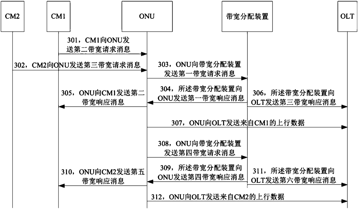
[0104] FIG. 2(b) is a flow chart of the bandwidth scheduling method provided in Embodiment 2 of the present application. In this embodiment, the first user-side device is CM1, the second user-side device is CM2, the first access device is OLT, and the message conversion device is set on the second access device, and the second access device is ONU. The actions related to message conversion performed by the ONU in the second embodiment may be performed by a message conversion device included in the ONU. The bandwidth scheduling method provided by Embodiment 2 of the present application will be described below with reference to FIG. 2( b ).

[0105] 301. CM1 sends a second bandwidth request message to an ONU.

[0106] To illustrate, the CM1 in the second embodiment may be the CM in the embodiment. The second bandwidth request message may include first priority information in addition to the parameters included in the second bandwidth request message in Embodiment 1. The firs...


PUM


Abstract

The invention provides a bandwidth scheduling method. In the method, a bandwidth allocation device receives a bandwidth request message sent by a message conversion device, wherein the bandwidth request message comprises a bandwidth requirement, and the bandwidth requirement is a bandwidth needed by a user side to complete service transmission. The bandwidth required. The bandwidth allocation device performs calculation according to the bandwidth requirement to obtain first bandwidth grant information and second bandwidth grant information, wherein the first bandwidth grant information is bandwidth information corresponding to the service and allocated to user side equipment, and the second bandwidth grant information is bandwidth information corresponding to the service and allocated to second access equipment. The bandwidth allocation device transmits the first bandwidth grant information to the user side equipment through the message conversion device. The bandwidth allocation device transmits the second bandwidth grant information to the second access equipment through first access equipment.

Description

technical field [0001] The present application relates to the communication field, and in particular to a bandwidth scheduling method and device. Background technique [0002] figure 1 It is a schematic diagram of an existing bandwidth scheduling method. Such as figure 1 As shown, in the existing bandwidth scheduling method, the user side device sends a first bandwidth request message to the second access device, and the first bandwidth request message includes the bandwidth requirement of the user side device. After receiving the first bandwidth request message, the second access device allocates bandwidth to the user-side device according to the bandwidth requirement of the user-side device. The second access device sends a first bandwidth response message to the user-side device, where the first bandwidth response message carries bandwidth information allocated to the user-side device. The user side device may send uplink data to the second access device according to ...

Claims


Application Information

Patent Timeline
Patent Type & Authority Applications(China)
IPC IPC(8): H04L12/24H04Q11/00
CPCH04L41/0896H04Q11/0062H04Q2011/0086H04L47/781H04L47/826H04Q11/0067H04Q2011/0064H04L69/18H04W72/044H04W72/21
Inventor 郑若滨
Owner HUAWEI TECH CO LTD
Why Eureka
Try Eureka