Local communication system

a communication system and local communication technology, applied in transmission, hybrid switching system, time-division multiplexing selection, etc., can solve the problems of reducing the smoothness of each connection, bringing certain overheads, and increasing buffering requirements

Inactive Publication Date: 2005-03-08
COMM & CONTROL ELECTRONICS
View PDF23 Cites 117 Cited by
  • Summary
  • Abstract
  • Description
  • Claims
  • Application Information

AI Technical Summary

Problems solved by technology

Known proposals for carrying variable rate data between different stations adopt a purely packet-based protocol, which brings certain overheads and also reduces smoothness of each connection, increasing buffering requirements at the source and destination.

Method used


Image

  • Local communication system
  • Local communication system
  • Local communication system

Examples


— example ii

High Speed Network—Example II

FIGS. 31 and 32 illustrate the block and frame structure of a second High Speed (HS) Network example. This provides both variable and fixed rate channels, but with flexible allocation of bytes within a common source data channel. Notable changes and new features relative to Example I above are explained as follows and new features:

The delay at each network node in processing each frame of Example I is greater than 1 subframe when using a network containing both Single Speed and High Speed network nodes. While this is not a problem in principle, it does not provide. Compatibility with the known D2B Optical network, which can only handle a maximum of one sub-frame delay around the ring. One possible solution to this is adopted in Example II, so that the maximum delay is 12 High Speed bits (=3 D2B Optical bits). Therefore, the constraint of one frame delay can be met up to a theoretical limit of 20 nodes. After accounting for typical processing delays throu...

example iii

also provides more detail of the control of variable with channel allocation, and a pocket structure for data within the variable rate channels.

Although the variable width channels and the fixed rate channels are again allocated within a single source data field from different ends, in this Example the variable with traffic is allocated in the source bytes from the beginning of the frame, not the end. At the start of each block of 48 frames, variable width block (VCB) headers are provided which indicate a channel ID and channel width which are fixed for the remainder of that block. The header for successive channels is found by counting through the source data bytes of the first frame in accordance with the width of each channel. The fixed rate data channels are allocated from the end of the source data field.

Packets carrying 42 bytes of source data in this example can also be grouped into packs of up to 256 packets. This can assist data handling in applications where larger segment...
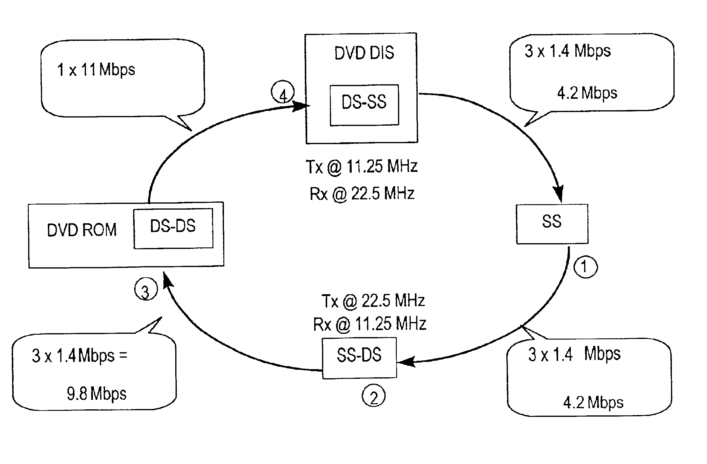
example application

The example system shown in FIG. 33 consisting of a DVD server acting as a source for 4 different video signals could make use of the source data field structure shown in FIG. 51. The bit rate allocation may be varied for each connection by varying the number of bytes allocated to the Variable Connection in each source data block (the width of the variable connection). Note again that since the destinations for the video signals are distributed around the system, not all variable-rate connections need to be present in all links in the system. For example, the variable-rate connection carry the video signal to Screen 1 (video 1) needs only to be present in the link from the DVD server to Screen 1. Each of the variable-rate connections could have a starting width of e.g. 24 bytes (per frame) and then could be varied individually as required by the rate of consumption in the MPEG decoder in each screen.

Variable Rate Flow Control Mechanism

While a source device directly controls the rate...


PUM


Abstract

Examples of local communication systems are disclosed, based on a ring of point-to-point links, providing for transport of fixed rate synchronous, fixed rate asynchronous data and variable rate data in a flexible format. Different segments of the ring network can carry data at different bit rates, while remaining synchronized to a common frame rate and having a common control channel structure, for compatibility with earlier systems. Parallel channels are provided, either permanently or when required, for signalling errors of source data, data validity/padding, flow control. Parallel variable width channels are defined with free content (stream or packet). Null data symbols are defined for padding on a byte-by-byte basis. The allocation of capacity among variable width channels is revised block by block, and a transition period is defined to allow for ring latency. Calculations for allocation of capacity are performed during one block for the next block, locally at each source station, according to predetermined rules. Information as to bandwidth requirements is exchanged prior to the calculation via a special connection signalling channel and message format.

Description

BACKGROUND OF THE INVENTION(1) Field of the InventionThe invention relates to a local communication system wherein plural stations are connected in a ring topology. The invention provides a novel local communication system, and stations and interface components for use in such a system.(2) Related ArtA local communication system which combines source data (CD audio, MPEG video, telephone audio etc) with control messages in a low cost fibre network has been proposed in the form of D2B Optical. For details, see for example the “Conan Technology Brochure” and the “Conan IC Data Sheet” available from Communication & Control Electronics Limited, 2 Occam Court, Occam Road, The Surrey Research Park, Guildford, Surrey, GU2 SYQ (also http: / / www.candc.co.uk). See also German patent applications of Becker GmbH with filing numbers 19503206.3 (95PO3), 19503207.1 (95PO4), 19503209.8 (95PO5), 19503210.1 (95PO6), 9503212.8 (95P07), 19503213.6 (95P08), 19503214.4 (95P09) and 19503215.2 (95P10). “Con...

Claims


Application Information

Patent Timeline
Patent Type & Authority Patents(United States)
IPC IPC(8): H04Q11/04H04L12/43H04L12/64H04L12/427H04L12/56H04L12/70
CPCH04L12/43H04L12/6418H04Q11/0478H04J2203/0066H04L2012/5612H04L2012/5662H04L2012/6437H04L2012/6467H04L2012/6483H04L2012/6486H04L2012/6489H04L2012/6497H04L2012/6456
Inventor STIRLING, ANDREW J.PENDERGAST, SIMON E.PARMAR, HARIVADEN A.
Owner COMM & CONTROL ELECTRONICS
Why Eureka
Try Eureka