
Duplex fiber optic connector plug

A technology of optical fiber connector and optical fiber socket, which is applied in the direction of light guide, optics, instruments, etc., can solve the problems of time-consuming and laborious, the lack of versatility of optical fiber connectors, and the inconvenience of construction personnel in the computer room, so as to achieve the effect of improving convenience

Active Publication Date: 2015-07-29
JYH ENG TECH
View PDF9 Cites 11 Cited by
  • Summary
  • Abstract
  • Description
  • Claims
  • Application Information

AI Technical Summary

Problems solved by technology

[0006] The above disclosed optical fiber connectors are all structurally modified from the original optical fiber connectors, and have no versatility at all for the optical fiber connectors that have been installed in the early stage, and it will be time-consuming and laborious to replace all of them. , it is also quite inconvenient for the construction personnel of the computer room, so it is necessary to improve

Method used


Image

  • Duplex fiber optic connector plug
  • Duplex fiber optic connector plug
  • Duplex fiber optic connector plug

Examples


Embodiment Construction

[0020] In order to enable your review committee members to clearly understand the content of the present invention, only the following descriptions are used together with the drawings, please refer to them.

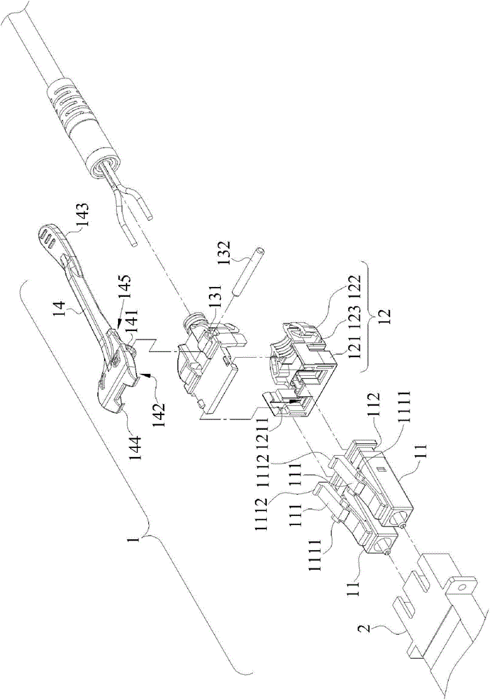
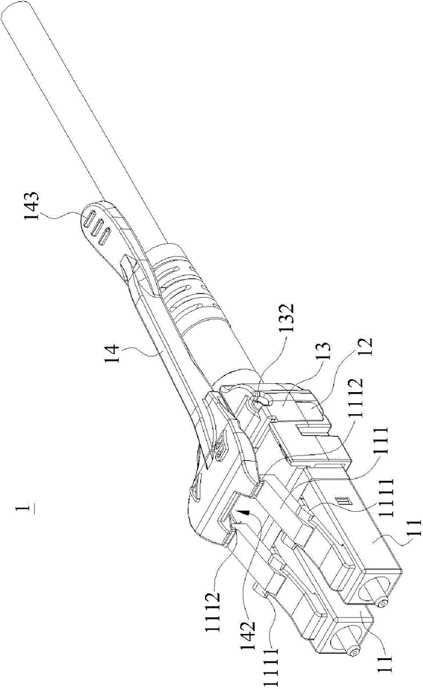
[0021] see figure 1 , figure 2 , image 3 and Figure 4 ~ Figure 5 , is an exploded perspective view of a preferred embodiment of the present invention, its assembled perspective appearance view and cross-sectional view, as well as schematic diagrams of various usage states during operation. As shown in the figure, the duplex fiber optic connector plug 1 of the present invention is used to connect a fiber optic receptacle 2 to complete the signal connection. The duplex fiber optic connector plug 1 includes a pair of fiber optic connectors 11 and a first housing 12. , a second housing 13 and a release lever 14 .

[0022] Wherein the surface of each optical fiber connector 11 has a release elastic piece 111, the release elastic piece 111 extends obliquely upward along ...


PUM


Abstract

A duplex fiber optic connector plug includes at least one fiber optic connector, a first casing, a second casing and a release lever. The release lever is axially coupled to a surface of the first casing and has an end coupled to a release bracket of the fiber optic connector to form a seesaw design. During operation, the release lever is compressed by the force of the finger, so that an end of the release lever is elevated, and the other end compresses the release bracket downward to release from a fiber optic socket, so as to provide an intuitively convenient operation and improve the convenience of use.

Description

technical field [0001] The invention relates to the field of optical fiber connectors, in particular to a plug structure applied to duplex optical fiber connectors, which can be operated in a push-up manner. Background technique [0002] Traditional network communication technologies mostly use copper metal wires as network jumpers to connect different cabinets in the network computer room, and can be used as a medium for data transmission through electrical signal transmission. However, with the development of network technology and the increasing amount of information, the general transmission of electrical signals has gradually become insufficient. Therefore, optical signals with faster transmission speeds are used for data transmission. This method is mostly used in the connection of mainframe computer rooms, for example: the local network of the telecommunications bureau is connected to the computer room of a community building or an office building. [0003] As more a...

Claims


Application Information

Patent Timeline
Patent Type & Authority Applications(China)
IPC IPC(8): G02B6/38
CPCG02B6/3893G02B6/3879
Inventor 林宴临
Owner JYH ENG TECH
Learn More