
Traffic flow management in a communications network

a traffic flow and communications network technology, applied in the field of control of traffic flow in the communications network, can solve the problems of inability to use in congestion price feedback control schemes, inability to effectively allocate bandwidth, and inherently bursty nature of the network, so as to discourage users from abusing the network and improve the overall resource utilization

Inactive Publication Date: 2008-04-22
RPX CLEARINGHOUSE
View PDF47 Cites 117 Cited by
  • Summary
  • Abstract
  • Description
  • Claims
  • Application Information

AI Technical Summary

Benefits of technology

[0013]In our arrangement and method, overall resource utilization is optimised by the use of congestion price based feedback that separates out the components of price that affect the mean traffic flow from the standard deviation of the flow. It is well known that on aggregation, standard deviations add according) to a square route law and means add linearly. In a mixed traffic flow type network, a network flow optimisation process that separates these components can provide improved overall resource utilization. A further advantage of this arrangement and method is that it enables a fairer allocation of ‘network-price’ to any given ingress flow. Rather than simply allocating the network charges on the basis of mean ingress flow, the charges are based on a measure of mean and standard deviation. This discourages users from abusing the network by sending excessively bursty traffic, unless it is genuinely important to the user. It should be noted that the terms prices and charges as employed herein refer to an internal network currency used for admission control purposes and is generally separate from any real billing.

Problems solved by technology

A particular problem that has been experienced with certain types of traffic, particularly data traffic and real-time video traffic, is its inherently bursty nature.
Further, this burstiness occurs on a timescale that is shorter than feasible network control loop timescales, and thus can lead to congestion when traffic is heavy.
Unfortunately, effective bandwidths do not add linearly on aggregation and so are difficult to use in a congestion price feedback control scheme.

Method used


Image

  • Traffic flow management in a communications network
  • Traffic flow management in a communications network
  • Traffic flow management in a communications network

Examples


Embodiment Construction

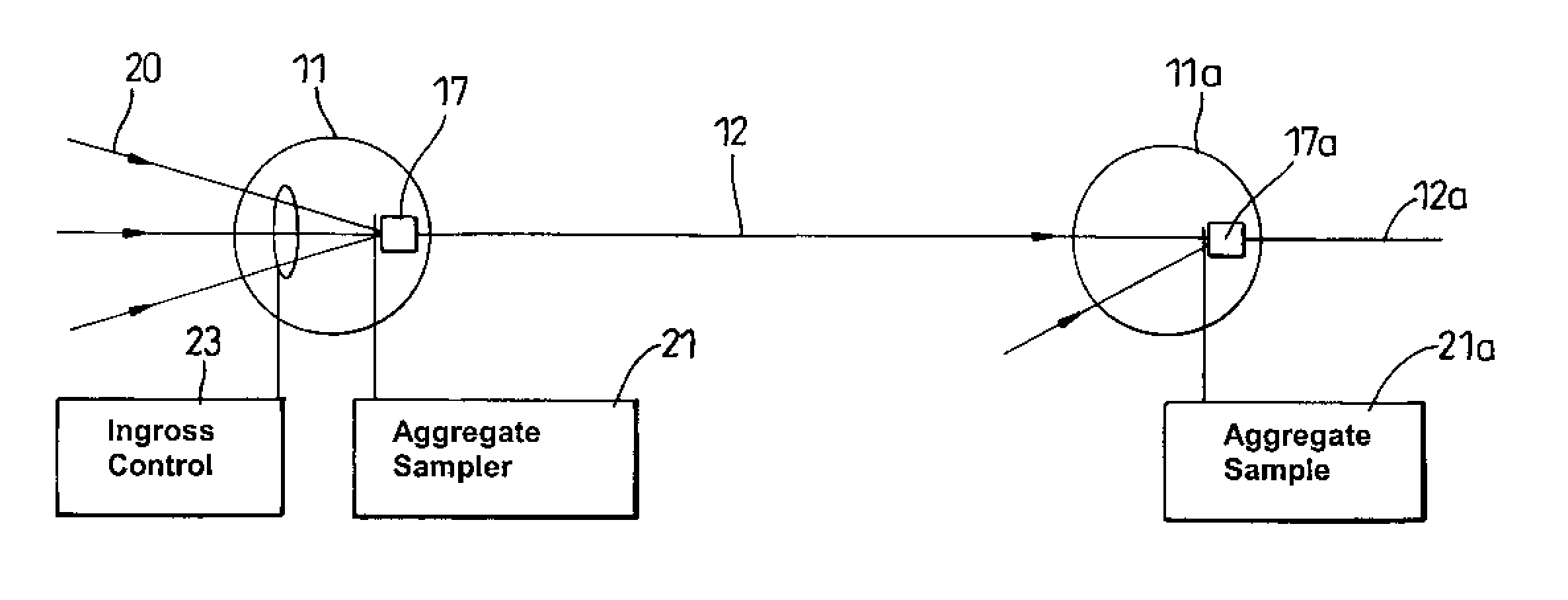
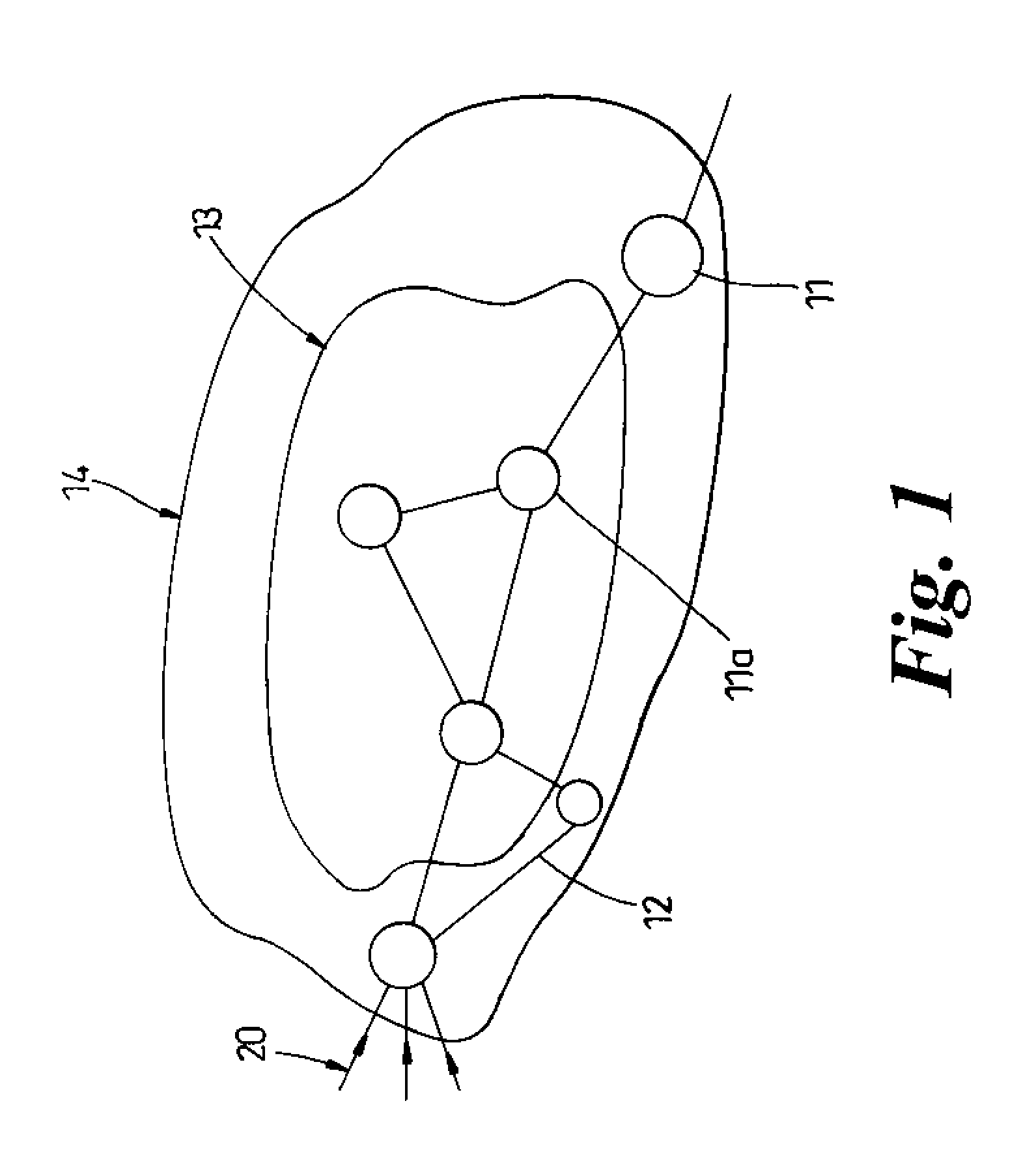
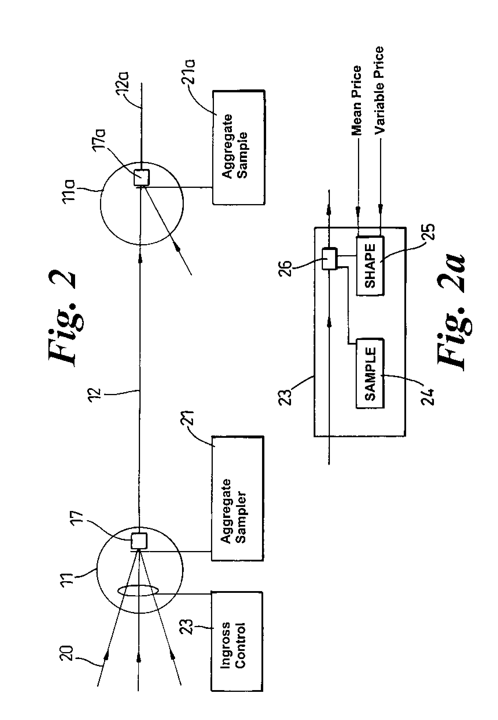
[0022]Referring first to FIG. 1, this shows an exemplary network in schematic form. As shown in FIG. 1, the network comprises a number of nodes 11, 11a interconnected by links 12. As shown in FIG. 1, the network comprises a care region 13 accessed via an edge region 14. The links 12 are usually optical fiber links, particularly in the core region. Advantageously the network of FIG. 1 is an Internet Protocol (IP) or MPLS (multi protocol label switched) network in which traffic is transported in packet form. An objective of the resource control system is to control the ingress of IP and MPLS traffic in such a way that different traffic classes are treated optimally. In particular, delay sensitive classes of traffic must see minimal congestion inside any router or on entering any of the packet buffers at the entrance to each optical link.

[0023]Referring now to FIG. 2, this shows in schematic form a an edge node 11 and a core network node 11a. At the edge node 11, a number of input traf...


PUM


Abstract

Admission of rapidly varying traffic flows to a communications network is controlled by sampling the traffic flows each at an ingress, and sampling an aggregate flow of said flows at some or all of the resources used by the aggregate flow. From this sampling, a mean bandwidth requirement for each traffic flow and a measure of the variance from that mean are determined. First and second prices for the mean and variance components of the controlled traffic flows that are calculated. These price calculations are used to determine an admission cost for each said flow so as to regulate the admission of that flow via a feedback price mechanism.

Description

FIELD OF THE INVENTION[0001]This invention relates to methods and apparatus for controlling traffic flow in a communications network so as to reduce congestion.BACKGROUND OF THE INVENTION[0002]Increasing volumes of communications traffic are now being carried on packet networks, and in particular on Internet Protocol (IP) networks. Such networks comprise nodes or routers interconnected by links so as to define a mesh. A recent introduction has been the concept of a network having an optical core in which traffic is carried on switched optical fiber paths between routers. The core is accessed by an edge networks Typically in the design of high capacity IP networks. routers are classified as either core routers or edge routers. Edge routers carry out all the network ingress and egress functions, in particular controlling the incoming traffic streams across the network. Core routers act as transit routers forwarding network traffic from one network node to another.[0003]In such a netwo...

Claims


Application Information

Patent Timeline
IPC IPC(8): G06F13/00H04L12/56
CPCH04L12/5695H04L47/11H04L47/15H04L47/263H04L47/788H04L47/822H04L47/825H04L47/70
Inventor KIRKBY, PAULHAMER, PETER
Owner RPX CLEARINGHOUSE
Learn More