
Distributed wireless network with dynamic bandwidth allocation

a wireless network and distributed wireless technology, applied in the field of communication networks, can solve the problems of difficult optimal allocation of transmission bandwidth to individual communication nodes, unpredictable bandwidth allocation, and limited network total available bandwidth, so as to increase and decrease the data communication bandwidth of said communication nodes, the effect of increasing and decreasing the data communication bandwidth

Inactive Publication Date: 2007-08-16
HONG KONG APPLIED SCI & TECH RES INST
View PDF12 Cites 112 Cited by
  • Summary
  • Abstract
  • Description
  • Claims
  • Application Information

AI Technical Summary

Benefits of technology

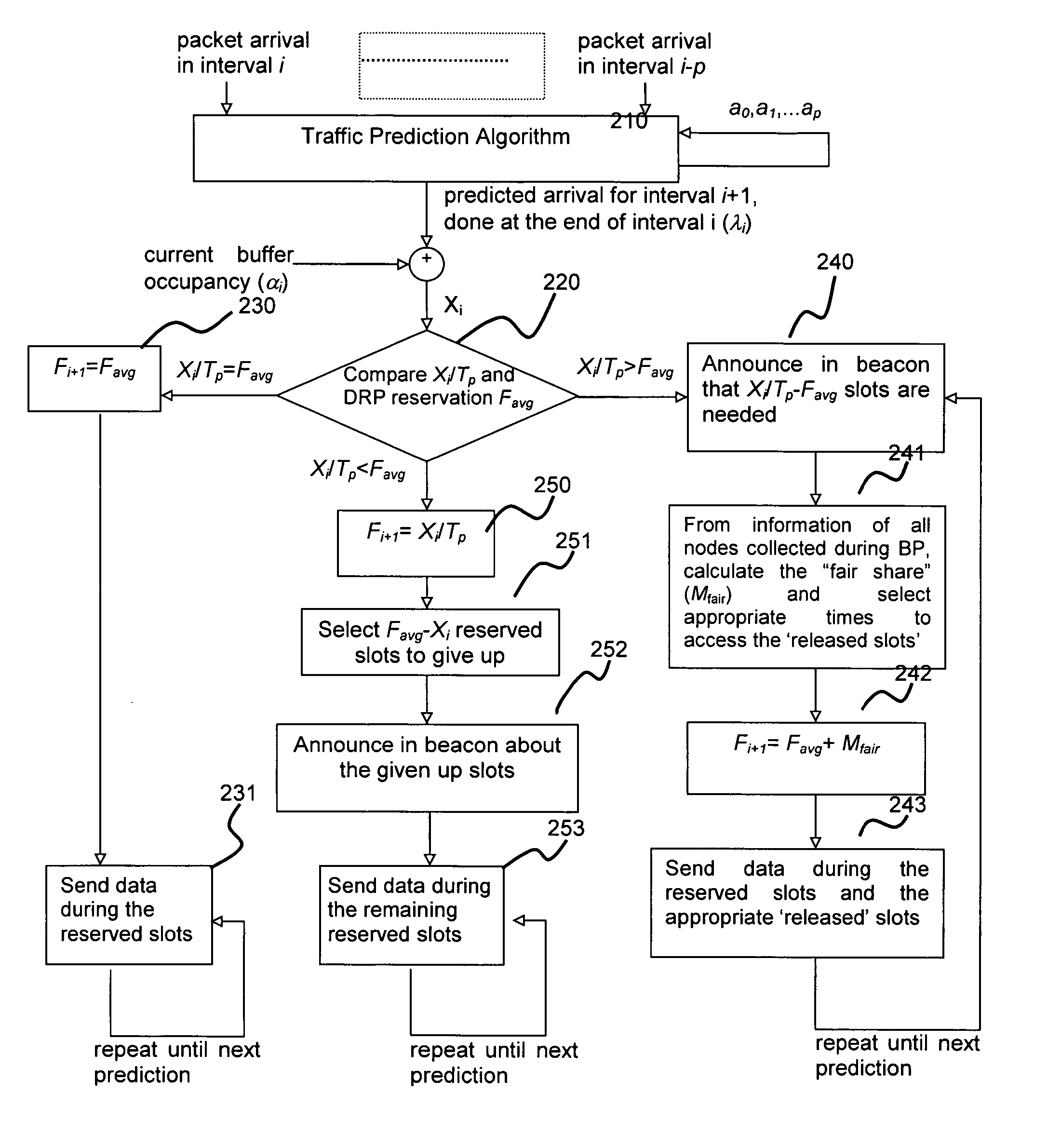
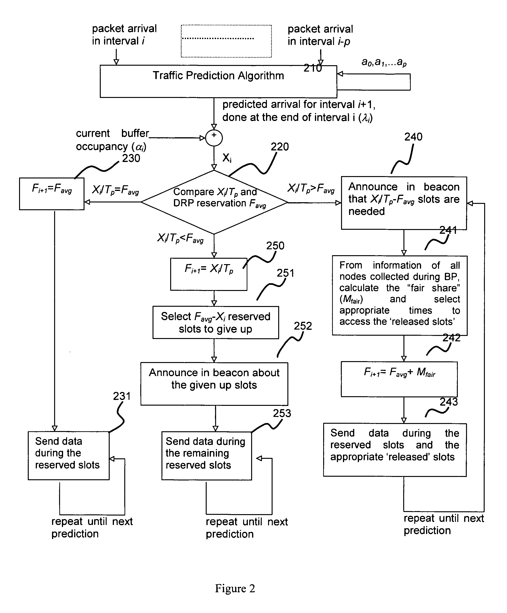
[0012] This dynamic bandwidth allocation facilitates efficient bandwidth utilization in a distributed communication network.
[0027] Preferably, said means for causing data communication in said distributed network can increase as well as decrease the data communication bandwidth of said communication node, the increase and decrease in data communication bandwidth is broadcast in said communication network during the beacon period.

Problems solved by technology

In a data communication network, the total available bandwidth on the network is always limited and each communication node will have to compete for an adequate amount of bandwidth in order to transmit data to fulfil an expected QOS level.
For such a distributed communication network, an optimal allocation of transmission bandwidth to the individual communication nodes is a difficult task.
However, this kind of access methods usually result in a schedule that does not take into account the service requirements or priorities of different traffic and are therefore not desirable, since a reasonable level of quality of service cannot be guaranteed.
When data traffic of the same priority is competing for a limited available bandwidth, the resulting bandwidth allocation can be somewhat unpredictable.
A bandwidth allocation scheme operating on the assumption of a known bandwidth requirement will not be optimal.

Method used


Image

  • Distributed wireless network with dynamic bandwidth allocation
  • Distributed wireless network with dynamic bandwidth allocation
  • Distributed wireless network with dynamic bandwidth allocation

Examples


Embodiment Construction

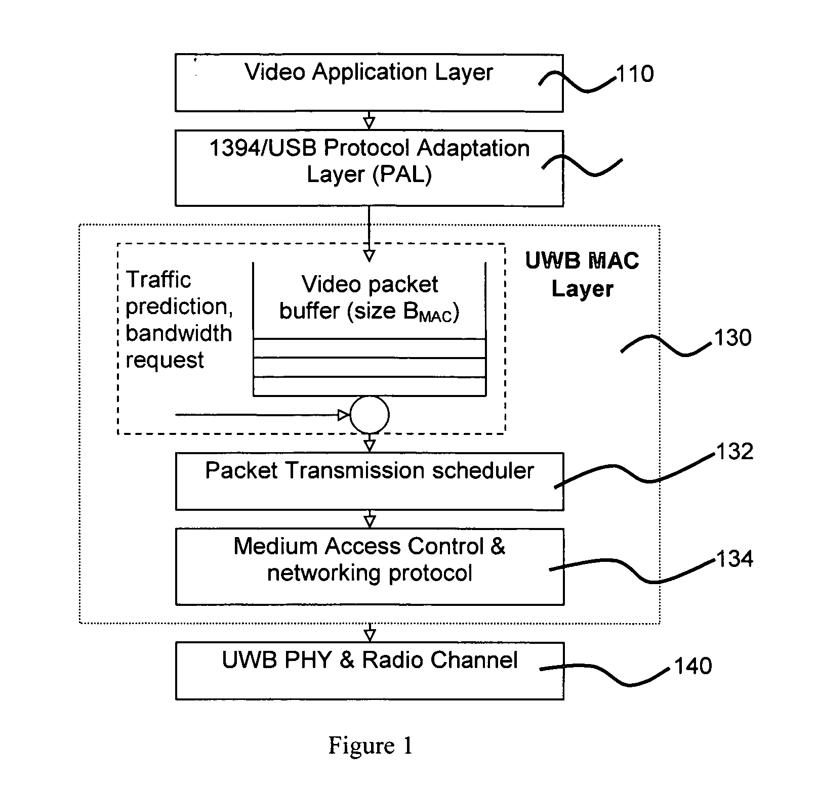
[0039] In the following, a decentralized network operating under the MBOA (Multi-Band OFDM Alliance) protocol will be explained as an implementation example of a communication network employing an exemplary distributed bandwidth allocation (DBA) scheme. However, it should be appreciated that the DBA scheme and devices of this invention is not limited to an MBOA system and can be applied to any ad hoc distributed communication networks, especially a network which support a “beacon” period and contention-based / reservation-based data period.

[0040] In order to facilitate understanding of the implementation example, a brief explanation will be given below concerning components of the MAC layer as defined by WiMedia MBOA (“MBOA MAC”).

[0041] In a MBOA MAC distributed network, there is no central controller which will define the formation and operation of the network. The communication nodes are connected to the network and share transmission bandwidth through a TDMA (Time Domain Multiple...


PUM


Abstract

A communication network includes a plurality of communication nodes, each of which can transmit data at a variable bandwidth. Each communication node predicts its own bandwidth requirements, and communicates its predicted own bandwidth requirements to the network. The nodes acquire bandwidth requirement information of other communication nodes on the network, and each one determines its own bandwidth allocation according to a common bandwidth allocation scheme. The common bandwidth allocation scheme is available to the plurality of communication nodes.

Description

FIELD OF THE INVENTION [0001] This invention relates to a communication network and, more particularly, to a distributed wireless communication network. More specifically, but not exclusively, this invention relates to a distributed wireless network with dynamic bandwidth allocation. BACKGROUND OF THE INVENTION [0002] A communication network which has the capability of allocating transmission bandwidth dynamically to a plurality of communication nodes connected to the network to meet the instantaneous traffic requirements of individual nodes is desirable to enhance quality of service (QOS). Dynamic bandwidth allocation is a broad term concerning methodology of allocating data transmission bandwidth in a communication network according to instantaneous requirements. In a data communication network, the total available bandwidth on the network is always limited and each communication node will have to compete for an adequate amount of bandwidth in order to transmit data to fulfil an e...

Claims


Application Information

Patent Timeline
IPC IPC(8): H04J1/16H04L12/16H04L12/56H04J3/22
CPCH04L12/5695H04L47/15H04L47/762H04W84/18H04L47/823H04W72/0453H04L47/783H04L47/70H04L47/83
Inventor WONG, WITTYFANG, ZU YUANDING, QUAN LONGDIU, PETER
Owner HONG KONG APPLIED SCI & TECH RES INST
Learn More