Communication system

a communication system and communication technology, applied in the field of communication systems, can solve the problems of difficult application of this technique in a communication system requiring low latency

Active Publication Date: 2018-03-22
HONDA MOTOR CO LTD
View PDF3 Cites 3 Cited by
  • Summary
  • Abstract
  • Description
  • Claims
  • Application Information

AI Technical Summary

Benefits of technology

[0005]Thus, an object of the present invention is to provide a communication system which is capable of realizing low latency data communications, together with improving network efficiency, by enabling all of the network nodes of a ring type network to simultaneously carry out data communications without causing the occurrence of data collision.
[0032]Further, in the fifth aspect of the invention, each of the network nodes further comprises a hop count register in which there are stored, at each time that the reception data is received by the data reception unit, the ID information and the hop count of each of the network nodes included within the reception data. Owing to this feature, since the content of the hop count register is updated each time that the reception data is received, each of the network nodes is capable of easily grasping the most recent positional relationship of the other network nodes with respect to the host network node, as well as the most recent state of connection of the other network nodes in the ring type network.

Problems solved by technology

However, if the transmission wait time is set randomly, it is difficult for this technique to be applied in a communication system requiring low latency, such as intra-body communications for a robot.

Method used


Image

  • Communication system
  • Communication system
  • Communication system

Examples


Embodiment Construction

[0051]A preferred embodiment of a communication system according to the present invention will be presented and described in detail below with reference to the accompanying drawings.

[Schematic Configuration of Communication System 10]

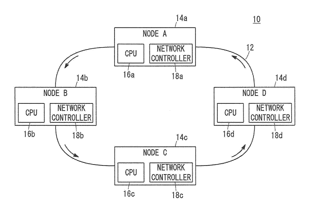
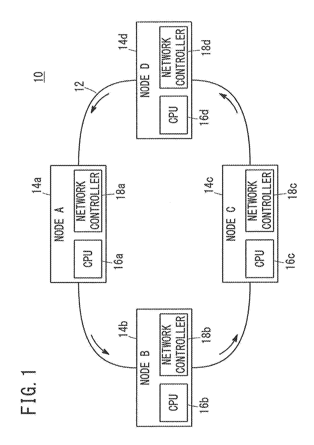
[0052]As shown in FIG. 1, the communication system 10 according to the present embodiment is a configuration in which a plurality of network nodes 14a to 14d are connected in a ring-like shape to a ring type network 12 which has a ring type of network topology. In the ring type network 12, each of the network nodes 14a to 14d performs unidirectional data communications in the direction of the arrows shown in FIG. 1. In the following description, the ring type network 12 is referred to simply as a network 12, and the network nodes 14a to 14d are also referred to simply as nodes 14a to 14d or nodes A to D. Further, in the present specification, in the case that a plurality of constituent elements are referred to collectively, for example, expressions usin...


PUM


Abstract

A communication system wherein, in each node, data transmission blocks transmit transmission data, and data relay blocks relay the transmission data from another node in a prior stage as relay data. Output switching units switch between outputting the transmission data and outputting the relay data as output data.

Description

TECHNICAL FIELD[0001]The present invention relates to a communication system that uses a ring type network in which a plurality of network nodes forms a ring-like shape, and performs communications in one direction.BACKGROUND ART[0002]In Japanese Laid-Open Patent Publication No. 2001-326663, it is disclosed that, in the case that a plurality of computers are connected to a token ring type of loop transmission path, a computer that has acquired a free token which circulates around the loop transmission path transmits transmission data and a busy token to a specified computer via the loop transmission path.SUMMARY OF INVENTION[0003]As described above, in conventional token passing system communications, a free token, which provides a right of transmission, is circulated within the loop transmission path (ring type network), and therefore, only a computer (network node) that has acquired such a free token is capable of transmitting transmission data.[0004]On the other hand, in an Ether...

Claims


Application Information

Patent Timeline
Patent Type & Authority Applications(United States)
IPC IPC(8): H04L12/24H04L29/06H04L12/933
CPCH04L41/0677H04L69/22H04L49/102H04L12/427H04L12/433
Inventor ISHIZAKI, RYUSUKE
Owner HONDA MOTOR CO LTD
Why Eureka
Try Eureka