Bait feeding device for fish pond

A technology for fish ponds and bait trays, which is applied in the field of bait feeding devices for fish ponds, can solve problems such as adverse effects on hand joints, rough feeding methods, poor feeding effects, etc., and achieves unbreakable, wide feeding range, low cost effect

Pending Publication Date: 2019-03-08
辛幼霞
View PDF0 Cites 1 Cited by
  • Summary
  • Abstract
  • Description
  • Claims
  • Application Information

AI Technical Summary

Problems solved by technology

[0002] Freshwater fish farming generally adopts the method of fish pond culture. A major problem facing fish pond culture is the problem of feeding feed. The existing method generally adopts the method of artificial feeding. This method has a large workload and will cause hand joints if it is carried out for a long time. Adverse effects, and when the fish pond is large, it cannot be fed to a long distance, and the feeding effect is not good
At present, there are also some feeding equipment that use compressed air to launch the bait, which is easy to damage the bait and cause the bait to be broken; at the same time, the feeding direction is fixed, the feeding method is rough, the actual feeding range is also small, and the noise is extremely loud

Method used


Image

  • Bait feeding device for fish pond
  • Bait feeding device for fish pond
  • Bait feeding device for fish pond

Examples


Embodiment 1

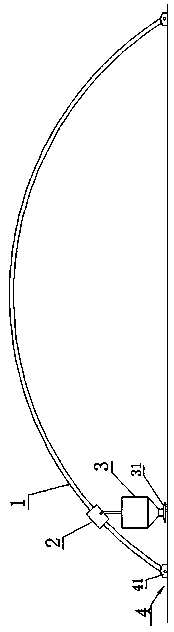
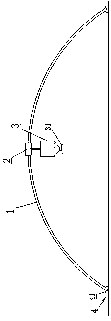
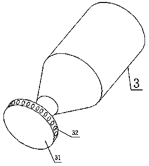
[0034] see Figure 1 to Figure 3 A baiting device for a fish pond, comprising an arch support column 1 fixed on the shore across the fish pond, a trolley 2 and a feeding box 3; the trolley 2 can move along the arch support column 1 to the upper part of the middle of the fish pond; The feeding box 3 is detachably suspended or fixed below the trolley 2, and moves with the trolley 2; the bottom of the feeding box 3 is an inverted cone; the bottom of the feeding box 3 is provided with a hollow rotating bait dish 31; the hollow rotating The bait throwing tray 31 is connected to the feeding box 3 by the bottom of the feeding box 3; the side of the hollow rotating bait throwing tray 31 is evenly provided with a plurality of bait outlet holes 32, so that the bait entering the hollow rotating bait throwing tray 31 moves downward under the action of centrifugal force. Divergent throw out.

[0035] Further, see Figure 4 , the middle part of the feeding box 3 is vertically provided wit...

Embodiment 2

[0045] see Figure 1 to Figure 3 A baiting device for a fish pond, comprising an arch support column 1 fixed on the shore across the fish pond, a trolley 2 and a feeding box 3; the trolley 2 can move along the arch support column 1 to the upper part of the middle of the fish pond; The feeding box 3 is detachably suspended or fixed below the trolley 2, and moves with the trolley 2; the bottom of the feeding box 3 is an inverted cone; the bottom of the feeding box 3 is provided with a hollow rotating bait dish 31; the hollow rotating The bait throwing tray 31 is connected to the feeding box 3 by the bottom of the feeding box 3; the side of the hollow rotating bait throwing tray 31 is evenly provided with a plurality of bait outlet holes 32, so that the bait entering the hollow rotating bait throwing tray 31 moves downward under the action of centrifugal force. Divergent throw out.

[0046] Further, see Figure 4 , the middle part of the feeding box 3 is vertically provided with ...


PUM


Abstract

The invention relates to a bait feeding device for a fish pond. The bait feeding device comprises an arch supporting column stretching across the fish pond and fixed to the shore, a trolley and a baitfeeding box; the trolley can move to the position above the middle of the fish pond along the arch supporting column; the bait feeding box is detachably hung on or fixed to the lower portion of the trolley to move along with the trolley; the bottom of the bait feeding box is in an inverted cone shape; a hollow rotary bait throwing disc is arranged on the lower portion of the bait feeding box andcommunicated with the inside of the bait feeding box through the bottom of the bait feeding box; a plurality of bait discharging holes are uniformly formed in the side surface of the hollow rotary bait throwing disc, so that bait in the hollow rotary bait swinging disc is thrown away under the centrifugal force effect; the bait feeding device for the fish pond can replace manual feeding, the feeding range is large, the feeding mode is mild, and the feeding range is wide.

Description

technical field [0001] The invention relates to a bait feeding device for fish ponds, belonging to the field of aquatic product cultivation equipment. Background technique [0002] Freshwater fish farming generally adopts the method of fish pond culture. A major problem facing fish pond culture is the problem of feeding feed. The existing method generally adopts the method of artificial feeding. This method has a large workload and will cause hand joints if it is carried out for a long time. Adverse effects, and when the fish pond is large, it cannot be fed to a long distance, and the feeding effect is not good. At present, there are also some feeding equipment that use compressed air to launch the bait, which is easy to damage the bait and cause the bait to be broken; at the same time, the feeding direction is fixed, the feeding method is rough, the actual feeding range is also small, and the noise is extremely loud . Contents of the invention [0003] In order to solve...

Claims


Application Information

Patent Timeline
Patent Type & Authority Applications(China)
IPC IPC(8): A01K61/80
CPCA01K61/80Y02A40/81
Inventor 辛幼霞
Owner 辛幼霞
Why Eureka
Try Eureka