Pneumatic feeding machine

A bait feeder and pneumatic technology, applied in climate change adaptation, fish farming, application, etc., can solve the problems of poor feeding effect, adverse effects on hand joints, and large workload, so as to increase the range of feeding, and increase the range of feeding. The effect of wide feeding range and preventing bait accumulation

Pending Publication Date: 2019-03-08
辛幼霞
View PDF0 Cites 0 Cited by
  • Summary
  • Abstract
  • Description
  • Claims
  • Application Information

AI Technical Summary

Problems solved by technology

[0002] Freshwater fish farming generally adopts the method of fish pond culture. A major problem facing fish pond culture is the problem of feeding feed. The existing method generally adopts the method of artificial feeding. This method has a large workload and will cause hand joints if it is carried out for a long time. Adverse effects, and when the fish pond is large, it cannot be fed to a long distance, and the feeding effect is not good

Method used


Image

  • Pneumatic feeding machine
  • Pneumatic feeding machine
  • Pneumatic feeding machine

Examples


Embodiment Construction

[0022] The present invention will be described in detail below in conjunction with the accompanying drawings and specific embodiments.

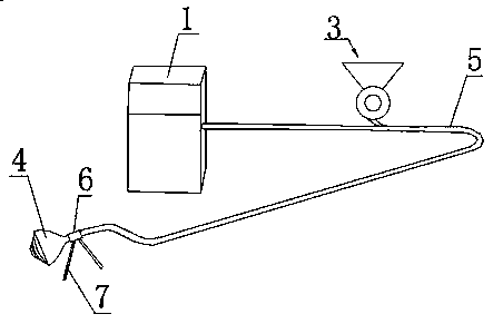
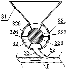
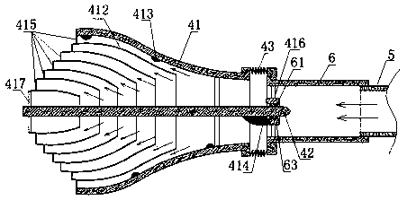
[0023] see Figures 1 to 4 , a pneumatic bait feeding machine, comprising a feeding pipe 5 and a fan 1, a feeder 3 and a sprayer 4 arranged in sequence; the fan 1 communicates with the front end of the feeding pipe 5 to input compressed air into it; the sprayer The feeder 4 communicates with the end of the feed pipe 5 to spray bait outward; the feeder 3 bypasses the feed pipe 5 in the middle of the feed pipe 5 and fills it with bait; the feeder 3 includes The feeding hopper 31, the material distribution chamber 32 and the material introduction pipe 33 arranged in sequence from top to bottom; The swivel 322 with sealing fit; the bottom of the feeding hopper 31 is connected to the inside of the outer cylinder 321 from the upper part of the outer cylinder 321; the upper end of the feeding pipe 33 is connected to the inside of the outer cylinder...


PUM


Abstract

The invention relates to a pneumatic feeding machine. The pneumatic feeding machine comprises a material conveying pipe, a fan, a feeder and a material ejector, wherein the fan, the feeder and the material ejector are arranged in sequence; the fan is communicated with the front end of the material conveying pipe to convey compressed air into the material conveying pipe; the material ejector is communicated with the tail end of the material conveying pipe to eject bait materials to the outside; the feeder is laterally communicated with the material conveying pipe from the middle of the materialconveying pipe to load the bait materials into the material conveying pip and comprises a feeding hopper, a material distribution chamber and a material guiding pipe which are sequentially arranged from top to bottom; the material distribution chamber comprises a flat outer cylinder body and a rotating body, wherein the outer cylinder body sleeves the rotating body, and the rotating body is in sealed fit with the inner circumferential wall of the outer cylinder body; the bottom of the feeding hopper is communicated with the interior of the outer cylinder body from the upper portion of the outer cylinder body; the upper end of the material guiding pipe is communicated with the interior of the outer cylinder body from the lower portion of the outer cylinder body; the lower end of the material guiding pipe is communicated with the material conveying pipe. Multiple material distribution cavities are uniformly formed in the outer circumference of the rotating body and are in sealed slidingfit with the inner circumferential wall of the outer cylinder body.

Description

technical field [0001] The invention relates to a pneumatic bait feeding machine, which belongs to the field of aquatic product breeding equipment. Background technique [0002] Freshwater fish farming generally adopts the method of fish pond culture. A major problem facing fish pond culture is the problem of feeding feed. The existing method generally adopts the method of artificial feeding. This method has a large workload and will cause hand joints if it is carried out for a long time. Adverse effects, and when the fish pond is large, it cannot be fed to a long distance, and the feeding effect is not good. Contents of the invention [0003] In order to solve the above technical problems, the present invention provides a pneumatic bait throwing machine. The pneumatic bait feeder can replace manual feeding, and has a large feeding range and a wide feeding range. [0004] Technical scheme of the present invention is as follows: [0005] A pneumatic bait feeding machine,...

Claims


Application Information

Patent Timeline
IPC IPC(8): A01K61/80
CPCA01K61/80Y02A40/81
Inventor 辛幼霞
Owner 辛幼霞
Why Eureka
Try Eureka