
A method of manufacturing an integrated base for blade measurement

A base and blade technology, applied in the field of integrated base manufacturing, can solve the problems of delayed production cycle, increased difficulty in tooling maintenance, and long time consumption, and achieves the effect of reducing production cost and maintenance cost, and shortening measurement period.

Active Publication Date: 2020-09-11
CHINA HANGFA SOUTH IND CO LTD
View PDF1 Cites 0 Cited by
  • Summary
  • Abstract
  • Description
  • Claims
  • Application Information

AI Technical Summary

Problems solved by technology

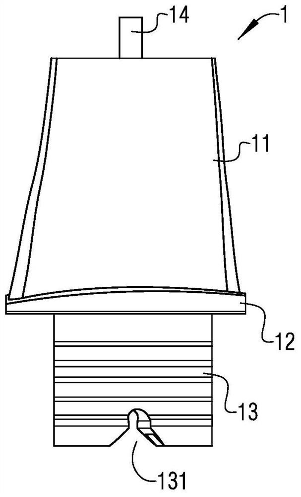
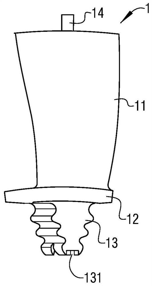
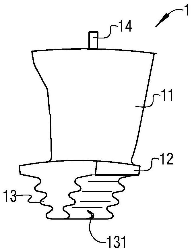
[0012] The above-mentioned existing measurement method is cumbersome and complicated. For example, when measuring the airfoil shape, use a vise to clamp the rolling rods 2 during the clamping process, and the levelness of the two rolling rods 2 will eventually affect the measured airfoil shape. The accuracy of the data, so the operator must be experienced to ensure the efficiency of the process of clamping the roller bar 2; and for the special measuring tool for measuring the edge plate 12 and the lock piece groove 131, such as Figure 2b and 2c As shown, if the gap between the mounting grooves is too large, it will be difficult to ensure the consistent state of the blades after clamping. If the gap is too small, it will be difficult to install the blades. Therefore, it is difficult to manufacture the mounting grooves and the accuracy is difficult to guarantee.
And in order to avoid damage to the blade, usually, the hardness of the material used to manufacture the special measuring tool (especially the position of the installation groove) will be less than the hardness of the material of the blade 1, so it is also easy to use during use. Causes wear of the mounting groove, which causes dimensional changes
[0013] In the measurement process, since each measurement part requires special tooling, multiple sets of special tooling are required for each blade, resulting in high production costs
In addition, the large number of tooling will also lead to difficult management, and the difficulty of tooling maintenance will increase
And because the whole process is manual operation, the clamping measurement process of each size requires the operator to have more skilled operation skills
[0014] Existing measurement process operating inefficiently
For each batch of at least hundreds of precision castings of various blades in actual production, since each blade needs to be measured, the measurement process takes a long time, which will become one of the important factors that delay the entire production cycle

Method used


Image

  • A method of manufacturing an integrated base for blade measurement
  • A method of manufacturing an integrated base for blade measurement
  • A method of manufacturing an integrated base for blade measurement

Examples


Embodiment Construction

[0041] In order to have a clearer understanding of the technical features, purposes and effects of the present invention, the specific implementation manners of the present invention will now be described with reference to the accompanying drawings. Wherein, the same parts adopt the same reference numerals.

[0042] Figure 1a It is a schematic diagram of a three-dimensional structure principle of a first-stage turbine blade; Figure 2a for right Figure 1a Schematic diagram of the principle of blade size measurement for the first-stage turbine blade; Figure 3a It is a schematic diagram of the principle of measuring the size of the turbine blade of the base made by using a method for manufacturing an integrated base for blade measurement according to a specific embodiment of the present invention; Figure 3b for right Figure 3a Schematic diagram of the principle of measuring the size of the flange of the turbine blade; Figure 3c for right Figure 3a Schematic diagram of...


PUM


Abstract

A method for manufacturing an integrated pedestal for blade measurement comprises the steps that step A, a casting cavity is built, and a blade is vertically lifted above the casting cavity; step B, alow melting point alloy is cast into the casting cavity built in the step A, and a rectangular-block blank is formed; and step C, the rectangular-block blank manufactured in the step B is subjected to local heat treatment, an alloy structure covering a locking plate groove is removed by melting, so that the locking plate groove is completely exposed. A rectangular block is manufactured. Through the method for manufacturing the integrated pedestal for blade measurement, by providing the standardized pedestal for blades, the blade measurement period is greatly shortened, and the production costand maintenance cost are effectively reduced.

Description

technical field [0001] The invention relates to the technical field of aero-engine production, in particular to a method for manufacturing an integrated base used for measuring blade parts during the production process of turbine blades of small and medium-sized aero-engines. Background technique [0002] In the manufacturing process of aero-engines, the turbine blades can be cast and formed by precision casting of individual blade parts, and then the individual blade parts are assembled on the edge plate to form the whole turbine. [0003] Figure 1a It is a schematic diagram of a three-dimensional structure principle of a first-stage turbine blade; Figure 1b It is a schematic diagram of a three-dimensional structure principle of a two-stage turbine blade; Figure 1c It is a schematic diagram of the three-dimensional structure principle of a free turbine blade; Figure 2a for right Figure 1a Schematic diagram of the principle of blade size measurement for the first-stag...

Claims


Application Information

Patent Timeline
Patent Type & Authority Patents(China)
IPC IPC(8): B23P15/04
CPCB23P15/04
Inventor 张小青梁涛王科昌周彭博蒋万里李怡
Owner CHINA HANGFA SOUTH IND CO LTD
Learn More