Fan blade and wind turbine with same

A technology for wind turbines and fan blades, applied in the field of wind turbines, can solve the problems of a small increase in the pressure coefficient of the pressure surface, and the improvement effect of the wind energy utilization rate cannot meet the needs of the industry.

Pending Publication Date: 2019-03-08
SINOMATECH WIND POWER BLADE
View PDF0 Cites 0 Cited by
  • Summary
  • Abstract
  • Description
  • Claims
  • Application Information

AI Technical Summary

Problems solved by technology

However, limited to the design of the above-mentioned turbulence structure of the existing fan blades, the leading edge energy absorption of the fan blades increased by the turbulence str

Method used


Image

  • Fan blade and wind turbine with same
  • Fan blade and wind turbine with same
  • Fan blade and wind turbine with same

Examples


Embodiment approach 2

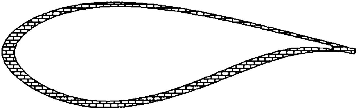
[0078] refer to Figure 10 , which representatively shows a schematic cross-sectional view of another embodiment of the fan blade proposed in the present disclosure. In this exemplary embodiment, the structure of the fan blade proposed in the present disclosure is substantially the same as that of the fan blade in the first embodiment. The main differences between the fan blade in this embodiment and the above-mentioned first embodiment will be described below.

[0079] like Figure 10 As shown, different from the design of the spoiler structure 210 (that is, the spoiler unit) in the first embodiment that is relatively close to the leading edge 103 of the blade body 100 in the chord direction F2, in this embodiment, the spoiler structure 210 is in the chord direction Up toward F2 is relatively close to the trailing edge 104 of the blade body 100 . Moreover, different from the curved design of the outer contour 211 of the flow spoiler structure 210 in the first embodiment, i...


PUM


Abstract

The invention provides a fan blade, which comprises a blade body and a turbulence structure. The turbulence structure is arranged on the pressure face of the blade body in the axial direction of the blade body, and a section figure of the turbulence structure has an outer contour away from the blade body; and the shape of the outer contour is a curve or a combination of the curve and a straight line. Through the turbulence structure arranged on the pressure face of the blade body, the flowing state of a fluid on the original aerofoil surface is changed, the flowing energy is absorbed at the position, close to the front edge of the blade body, of the turbulence structure, and the pressure coefficient of the pressure face is increased; and the aerofoil curvature degree is increased at the position, close to the rear edge of the blade body, of the turbulence structure, downstream flowing of the fluid is promoted, and thus the pressure coefficient of the pressure face is also increased.

Description

technical field [0001] The present disclosure relates to the technical field of wind power, in particular to a fan blade and a wind turbine with the fan blade. Background technique [0002] Aerofoils were used on wind turbine blades in the early days. With the development of technology in related industries, more and more wind turbine-specific airfoils have been applied to the shape design of wind turbine blades. like Figure 1 to Figure 3 As shown, the existing airfoil dedicated to wind turbines, especially the large-thickness airfoil, when the fluid runs on the pressure side of the fan blade (Pressure side, that is, the windward side, and the other side of the fan blade is the leeward side, Suction side), The pressure coefficient of some areas of the pressure surface is small (such as image 3 The dotted line area in is the area with low pressure coefficient), which reduces the utilization coefficient of wind energy and causes energy loss. [0003] In order to increase t...

Claims


Application Information

Patent Timeline
IPC IPC(8): F03D1/06
CPCF03D1/0633F03D1/0641F03D1/0675Y02E10/72
Inventor 周捍珑李磊方致阳乔玉军郝赫为李成良
Owner SINOMATECH WIND POWER BLADE
Why Eureka
Try Eureka