Single-action type piston compressor and air inlet control method thereof

A compressor and single-acting technology, applied in pump control, liquid variable capacity machinery, mechanical equipment, etc., can solve the problems of difficult air intake in the intake chamber and low cylinder pressure, so as to increase the gas pressure and reduce the pressure loss , the effect of increasing the pressure coefficient

Active Publication Date: 2019-12-31
XI AN JIAOTONG UNIV
View PDF6 Cites 1 Cited by
  • Summary
  • Abstract
  • Description
  • Claims
  • Application Information

AI Technical Summary

Problems solved by technology

[0003] The purpose of the present invention is to provide a single-acting piston compressor and its air intake control method, which can prevent the piston side from The escape of gas, improving the pressure coefficient, energy efficiency level and displacement of single-acting compressors with intake channels arranged on pistons

Method used


Image

  • Single-action type piston compressor and air inlet control method thereof
  • Single-action type piston compressor and air inlet control method thereof
  • Single-action type piston compressor and air inlet control method thereof

Examples


Embodiment 1

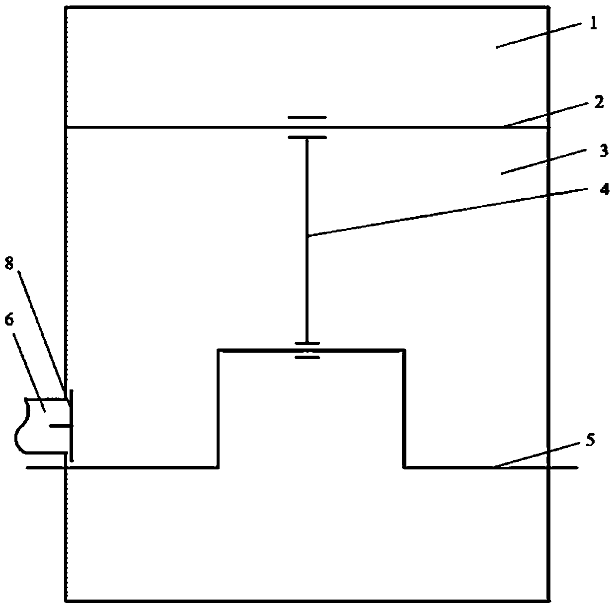
[0026] see figure 1 , The single-acting piston compressor of the present invention includes a cylinder 1, a piston 2, a connecting rod 4 and a crankshaft 5. When the compressor is working, the crankshaft 5 drives the piston 2 to reciprocate. This single-acting piston compressor sucks air through the suction port on the piston 2, which is provided with an intake valve, and the back of the piston 2 is an internal suction chamber 3 as a suction volume. The inner air suction chamber 5 is connected with the outer air suction chamber 7 through an air flow hole 6 , and a one-way valve 8 is arranged on the air flow hole 6 . When the piston 2 descends (the gas in the cylinder 1 expands and inhales), the one-way valve 8 is closed, so that the connection between the internal suction chamber 3 and the external suction chamber 7 is disconnected, preventing the gas in the internal suction chamber 3 from escaping; When the piston 2 goes up (the gas in the cylinder 1 is compressed and exhau...

Embodiment 2

[0029] Based on the scheme of embodiment 1, the one-way valve 8 of embodiment 1 is replaced by an automatic control valve 9, and the opening and closing time of the automatic control valve 9 is controlled by parameters such as piston stroke or crank angle, so as to realize when the piston 2 goes down ( When the gas in the cylinder 1 expands and inhales), the automatic control valve 9 is closed, so that the internal suction chamber 5 and the external suction chamber 7 are disconnected to prevent the gas in the internal suction chamber 5 from escaping; when the piston 2 goes up (the cylinder 1 During internal gas compression, exhaust), automatic control valve 9 is opened, and internal suction cavity 3 is communicated with external suction cavity 7, and internal suction cavity 3 is supplemented with gas through external suction cavity 7.

[0030] In this way, by forming a relatively closed internal suction chamber as the suction volume, the situation of gas escape caused by the do...

Embodiment 3

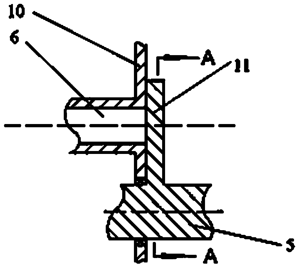
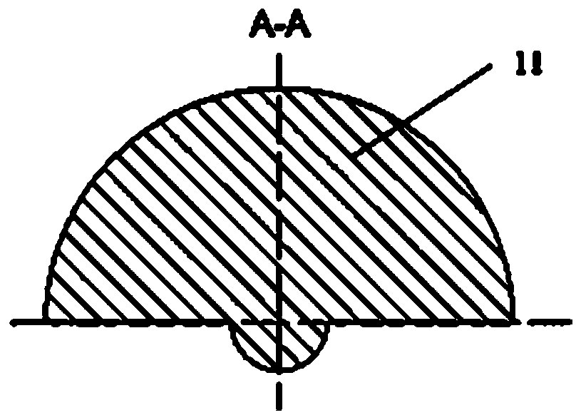
[0032] based on figure 1 The compressor structure shown is set on the crankshaft 5 image 3 Baffle 11 shown. The baffle plate 11 is semicircular, the bottom edge is connected with the crankshaft 5, and can rotate periodically with the crankshaft 5. The distance between the baffle plate 11 and the wall surface 10 of the inner suction cavity is very small. When the baffle plate 11 blocks the air flow hole 6, it will block the air flow hole 6, so that the air flow cannot pass through, and the connection between the internal suction cavity 3 and the external suction cavity 7 is disconnected. Connection; when the baffle plate 11 does not block the air flow hole 6, the inner suction chamber 3 and the outer suction chamber 7 can be communicated.

[0033] By rationally designing the shape and position of the baffle, it can be realized that when the piston 2 goes down (the gas in the cylinder 1 expands and inhales), the baffle 11 can block the air flow hole 6, so that the inner sucti...


PUM


Abstract

The invention discloses a single-action type piston compressor and an air inlet control method thereof. The single-action type piston compressor comprises an air cylinder and a piston arranged in theair cylinder, wherein the cavity of the air cylinder is divided by the piston to form an interior air suction cavity as an air suction volume; the interior air suction cavity is formed in the reverseside of the piston; an air suction opening with an air suction valve is formed in the piston; the interior air suction cavity is connected with an exterior air suction cavity through an airflow through hole; a switching mechanism is arranged on the airflow through hole; the piston is connected with a crankshaft through a connecting rod; the piston is driven by the crankshaft to do reciprocating motion; when the air cylinder sucks the air, the air in the air cylinder expands, the piston moves downwards, and the switching mechanism on the airflow through hole is closed, so that the interior airsuction cavity and the exterior air suction cavity are disconnected to prevent the air in the interior air suction cavity from escaping; and when the air cylinder exhausts air, the air in the air cylinder is compressed, the piston moves upwards, and the switching mechanism on the airflow through hole is opened, so that the interior air suction cavity and the exterior air suction cavity are communicated with each other, and the air is supplemented into the interior air suction cavity through the exterior air suction cavity. The single-action type piston compressor can avoid air on the piston side from fleeing.

Description

technical field [0001] The invention relates to the field of piston compressors, in particular to a single-acting piston compressor and an air intake control method thereof. Background technique [0002] The single-acting piston compressor is still widely used because of its advantages of low cost and high pressure gas discharge. Now there is a new type of single-acting piston compressor, the air intake hole is set on the piston, this arrangement can make the air intake chamber shift to the back of the piston, and the side of the valve cover only has the exhaust chamber, which can A larger area is left for the exhaust cavity, thereby reducing the air flow pulsation of the exhaust. But for this type of compressor, since the intake chamber is on the back of the piston, during the intake process, the piston is in motion, the volume of the intake chamber will change, and the gas in the intake chamber is pushed by the movement of the air valve. , resulting in difficulty in air ...

Claims


Application Information

Patent Timeline
Patent Type & Authority Applications(China)
IPC IPC(8): F04B39/00F04B39/10F04B39/12F04B49/22
CPCF04B39/0005F04B39/0016F04B39/10F04B39/122F04B39/128F04B49/225
Inventor 许良聪吴伟烽杨笑天郭天硕李许旺
Owner XI AN JIAOTONG UNIV
Why Eureka
Try Eureka