A single-acting piston compressor and its air intake control method
A control method and compressor technology, which is applied in pump control, liquid variable displacement machinery, mechanical equipment, etc., and can solve problems such as difficult air intake in the intake chamber and low cylinder pressure
- Summary
- Abstract
- Description
- Claims
- Application Information
AI Technical Summary
Problems solved by technology
Method used
Image
Examples
Embodiment 1
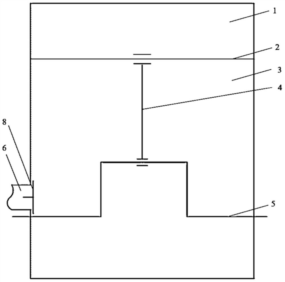
[0026] see figure 1 , The single-acting piston compressor of the present invention includes a cylinder 1, a piston 2, a connecting rod 4 and a crankshaft 5. When the compressor is working, the crankshaft 5 drives the piston 2 to reciprocate. This single-acting piston compressor sucks air through the suction port on the piston 2, which is provided with an intake valve, and the back of the piston 2 is an internal suction chamber 3 as a suction volume. The inner air suction chamber 5 is connected with the outer air suction chamber 7 through an air flow hole 6 , and a one-way valve 8 is arranged on the air flow hole 6 . When the piston 2 descends (the gas in the cylinder 1 expands and inhales), the one-way valve 8 is closed, so that the connection between the internal suction chamber 3 and the external suction chamber 7 is disconnected, preventing the gas in the internal suction chamber 3 from escaping; When the piston 2 goes up (the gas in the cylinder 1 is compressed and exhau...
Embodiment 2
[0029] Based on the scheme of embodiment 1, the one-way valve 8 of embodiment 1 is replaced by an automatic control valve 9, and the opening and closing time of the automatic control valve 9 is controlled by parameters such as piston stroke or crank angle, so as to realize when the piston 2 goes down ( When the gas in the cylinder 1 expands and inhales), the automatic control valve 9 is closed, so that the internal suction chamber 5 and the external suction chamber 7 are disconnected to prevent the gas in the internal suction chamber 5 from escaping; when the piston 2 goes up (the cylinder 1 During internal gas compression, exhaust), automatic control valve 9 is opened, and internal suction cavity 3 is communicated with external suction cavity 7, and internal suction cavity 3 is supplemented with gas through external suction cavity 7.
[0030] In this way, by forming a relatively closed internal suction chamber as the suction volume, the situation of gas escape caused by the do...
Embodiment 3
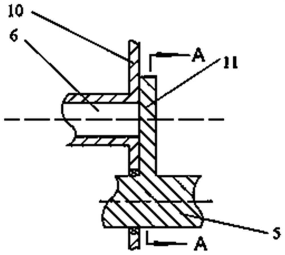
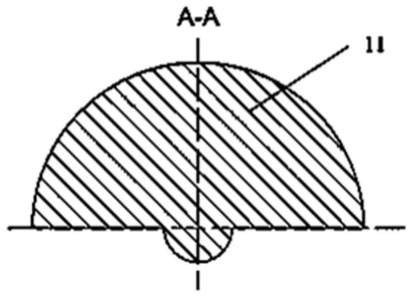
[0032] based on figure 1 The compressor structure shown is set on the crankshaft 5 image 3 Baffle 11 shown. The baffle plate 11 is semicircular, the bottom edge is connected with the crankshaft 5, and can rotate periodically with the crankshaft 5. The distance between the baffle plate 11 and the wall surface 10 of the inner suction cavity is very small. When the baffle plate 11 blocks the air flow hole 6, it will block the air flow hole 6, so that the air flow cannot pass through, and the connection between the internal suction cavity 3 and the external suction cavity 7 is disconnected. Connection; when the baffle plate 11 does not block the air flow hole 6, the inner suction chamber 3 and the outer suction chamber 7 can be communicated.
[0033] By rationally designing the shape and position of the baffle, it can be realized that when the piston 2 goes down (the gas in the cylinder 1 expands and inhales), the baffle 11 can block the air flow hole 6, so that the inner sucti...
PUM
 Abstract
Description
Claims
Application Information
 - R&D
- Intellectual Property
- Life Sciences
- Materials
- Tech Scout
- Unparalleled Data Quality
- Higher Quality Content
- 60% Fewer Hallucinations
Browse by: Latest US Patents, China's latest patents, Technical Efficacy Thesaurus, Application Domain, Technology Topic, Popular Technical Reports.
© 2025 PatSnap. All rights reserved.Legal|Privacy policy|Modern Slavery Act Transparency Statement|Sitemap|About US| Contact US: help@patsnap.com


