
Centrifugal ventilator

A centrifugal fan and eccentric technology, applied in the direction of mechanical equipment, machine/engine, liquid fuel engine, etc., can solve the problem that the centrifugal fan cannot meet the requirements of large flow coefficient and large pressure coefficient at the same time

Active Publication Date: 2014-02-26
TIANJIN UNIV
View PDF3 Cites 0 Cited by
  • Summary
  • Abstract
  • Description
  • Claims
  • Application Information

AI Technical Summary

Problems solved by technology

[0009] Therefore, the centrifugal fans in the prior art cannot meet the requirements of large flow coefficient and large pressure coefficient at the same time

Method used


Image

  • Centrifugal ventilator
  • Centrifugal ventilator
  • Centrifugal ventilator

Examples


Embodiment Construction

[0030] The centrifugal fan of the present invention will be described in detail below in conjunction with the embodiments and accompanying drawings.

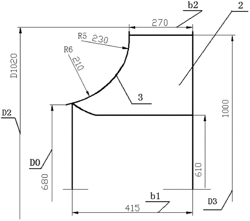
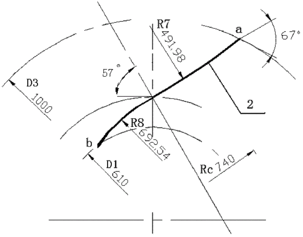
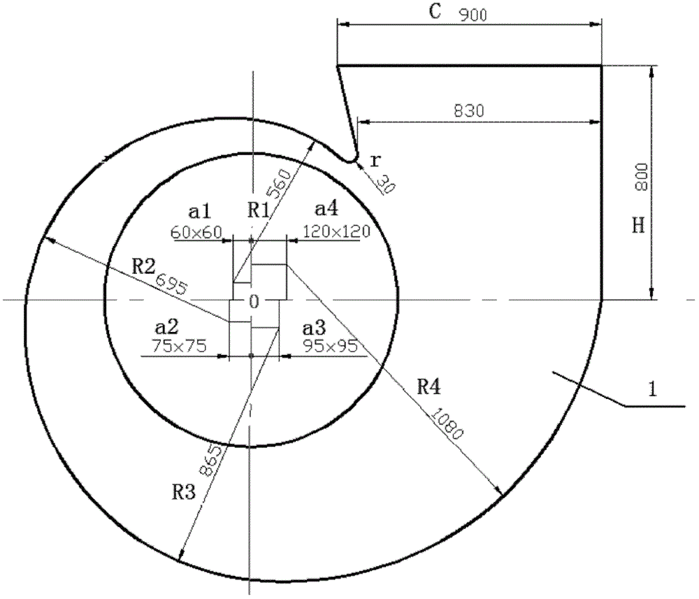
[0031] As shown in the figure, the centrifugal fan of the present invention includes a volute 1 of the centrifugal fan and an impeller 4 formed of a plurality of blades 2 in the volute 1 of the centrifugal fan, and the profile of the blade 2 is Two-dimensional double-arc structure, the two arcs have opposite bending directions, and are smoothly connected at a radius Rc of 730-750mm (optimally 740mm). The radii of R6 are 230mm and 210mm respectively; the profile line of the volute 1 in the circumferential direction is smoothly connected by segmented eccentric arcs.

[0032] Such as figure 2 As shown, the starting point and the end point of the 2-shaped line of the blade are to make an oblique straight line at the connection point with a tangent angle of 57° to the circle Rc, and to make a radius R7 of 417 to 417° on the oblique...


PUM


Abstract

A centrifugal ventilator comprises a volute casing thereof and an impeller, wherein the impeller consists of a plurality of blades and is arranged in the volute casing of the centrifugal ventilator. The profile of each blade is in a two-dimensional double-arc structure, the two arcs bend to opposite directions and are connected smoothly at the position with the radius Rc ranging from 730mm to 750mm, the profile of a cap of the impeller is in double-arc transitional connection, the radiuses of the two arcs are respectively 230mm and 210mm, the outlet of the impeller has a rotary diffuser structure, and the circumferential profile of the volute casing is in smooth sectional eccentric arc connection. The flow coefficient of the centrifugal ventilator is 0.24, which is increased by 40% as compared with that of the L6-46 centrifugal ventilator and is increased by 90% as compared with that of Y5-58 centrifugal ventilator; the pressure coefficient is 1.234, which is increased by 40% as compared with that of a T4-79 centrifugal ventilator, and is increased by 11% as compared with that of the Y5-58 centrifugal ventilator; and the efficiency of the centrifugal ventilator is 86%, which is close to the highest efficiency point of a high-flow low-pressure high-efficiency ventilator, and is higher than the maximum efficiency value of a medium-flow high-pressure ventilator.

Description

technical field [0001] The invention relates to a ventilator. In particular, it relates to a high-flow, high-pressure and high-efficiency centrifugal fan. Background technique [0002] A fan is a machine used to compress and transport gas. From an energy point of view, it is a machine that converts the mechanical energy of the prime mover into gas energy. The centrifugal fan is mainly composed of air inlet, impeller, volute and other main components. The centrifugal force generated by the rotation of the impeller makes the medium gain energy, and then part of the kinetic energy is converted into static pressure through the volute and the diffuser section at the exit of the volute. [0003] At present, among the large flow fans, typical products are 4-73, 5-60, 6-50 and other series fans, and their main parameters are shown in Table 3-1: [0004] Table 3-1 Main technical parameters of existing large flow fans [0005] [0006] The above data comes from "Fan Handbook", ...

Claims


Application Information

Patent Timeline
Patent Type & Authority Patents(China)
IPC IPC(8): F04D29/30F04D29/28F04D29/42
Inventor 刘正先郝维吴仲义陈丽英
Owner TIANJIN UNIV
Learn More