Hydraulic transmission structure with buffer structure

A technology of hydraulic transmission and buffer structure, applied in the directions of transmission parts, gear vibration/noise attenuation, belt/chain/gear, etc., can solve problems such as large impact force, limitations of applicability and practicality, mismatch of upper and lower strokes, etc. , to achieve reasonable structural settings, improve the stability and reliability of use, and good practicability.

Inactive Publication Date: 2019-03-08
林阿成
View PDF0 Cites 0 Cited by
  • Summary
  • Abstract
  • Description
  • Claims
  • Application Information

AI Technical Summary

Problems solved by technology

Due to the fast moving speed of the piston, the existing rigid output often has a large impact force; at the same time, it will cause the problem of mismatching the upper and lower strokes, so the applicability and practicability are limited, and it is difficult to meet the needs of the market.

Method used


Image

  • Hydraulic transmission structure with buffer structure

Examples


Embodiment 1)

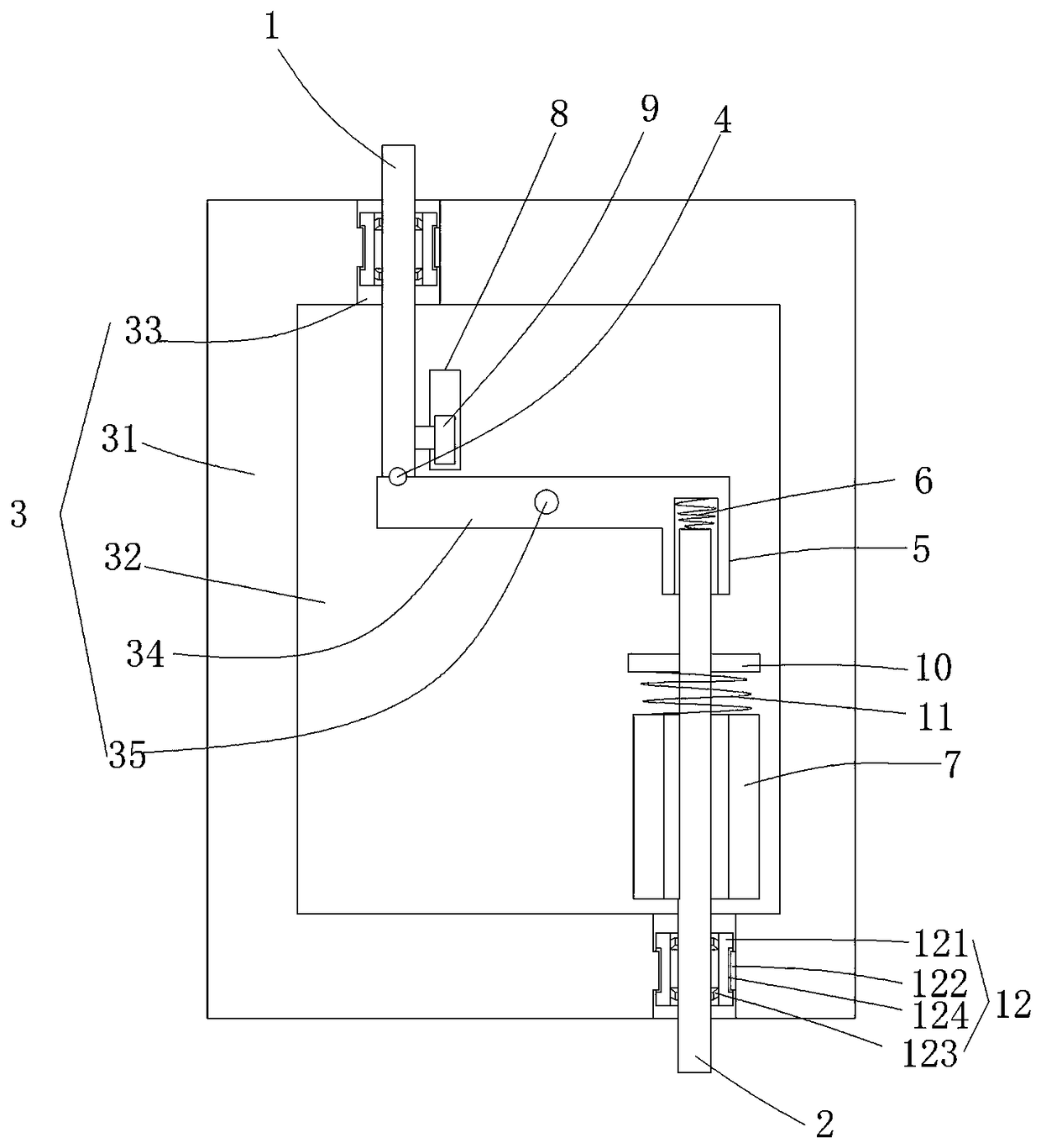
[0015] figure 1 An embodiment of the invention is shown in which figure 1 It is a schematic diagram of the structure of the present invention.

[0016] See figure 1 , a hydraulic transmission structure with a buffer structure, including a first transmission rod 1 and a second transmission rod 2, the first transmission rod is connected with the hydraulic structure, and the first transmission rod and the second transmission rod are A buffer connection structure 3 is arranged therebetween, and the buffer connection structure 3 includes a casing 31, a buffer cavity 32 is arranged in the casing, and the symmetrical side walls of the casing are fixed with the buffer concave The connecting circular hole 33 connected to the cavity is provided with a tilting rod 34 in the buffer cavity, and the middle part of the tilting rod is connected to the center of the buffer cavity through the rotating shaft 35, and the first transmission rod is connected through the connection The circular h...


PUM


Abstract

The invention discloses a hydraulic transmission structure with a buffer structure. The hydraulic transmission structure with the buffer structure comprises a first transmission rod and a second transmission rod, wherein a buffer connection structure is arranged between the first transmission rod and the second transmission rod; the buffer connection structure comprises a shell, a buffer cavity isformed in the shell; connecting circular holes are fixed to symmetrical side walls of the shell; a tilting rod is arranged in the buffer cavity; the middle part of the tilting rod is connected with the center of the buffer cavity through a rotating shaft; a buffer sleeve with one end which is closed is fixed to the other end of the tilting rod, one end of the second transmission rod penetrates through the connecting circular holes, and the end part of the second transmission rod is inserted and clamped in the buffer sleeve; and a buffer pressure spring is fixed between the second transmissionrod and the end wall of the buffer sleeve, and a guide convex body with a U-shaped cross section is arranged on the bottom wall of the buffer cavity. The hydraulic transmission structure with the buffer structure has reasonable structural arrangement and certain buffer performance, can reduce abrasion caused by rigid connection, is beneficial to improving the use stability and the use reliability, and has high applicability and good practicability.

Description

technical field [0001] The invention belongs to the technical field of mechanical hydraulic transmission structures, and in particular relates to a hydraulic transmission structure with a buffer structure. Background technique [0002] In mechanical hydraulic devices, the displacement of the piston is usually used to push the lower-level device, which is mainly connected by a strut, that is, a rigid output is used to directly transmit the displacement of the piston to the lower-level device. Due to the fast moving speed of the piston, the existing rigid output often has a large impact force; at the same time, it will cause the problem of mismatch between the upper and lower strokes, so the applicability and practicability are limited, and it is difficult to meet the needs of the market. SUMMARY OF THE INVENTION [0003] The purpose of the present invention is to provide a hydraulic transmission structure with a buffer structure with reasonable structural arrangement and st...

Claims


Application Information

Patent Timeline
Patent Type & Authority Applications(China)
IPC IPC(8): F16H57/00
CPCF16H57/0006
Inventor 林阿成
Owner 林阿成
Why Eureka
Try Eureka