Switch signal anti-shake discrimination method and switch signal anti-shake discrimination device

A technology of switch signal and discrimination method, which is applied in the direction of instruments, test/monitoring control systems, control/regulation systems, etc., and can solve the problems of multi-threshold discrimination of inability to switch state, inability to discriminate information of switch in anti-shake, etc.

Active Publication Date: 2020-01-07
HUNAN SANY INTELLIGENT CONTROL EQUIP
View PDF6 Cites 0 Cited by
  • Summary
  • Abstract
  • Description
  • Claims
  • Application Information

AI Technical Summary

Problems solved by technology
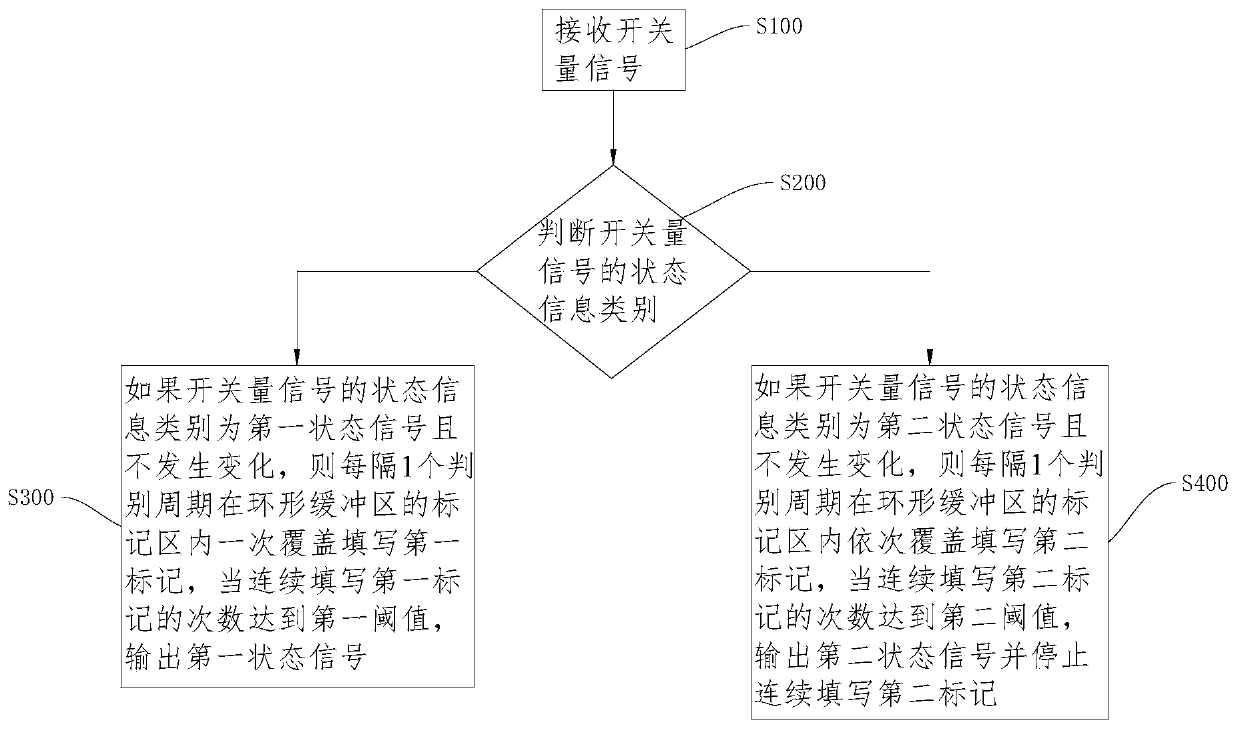
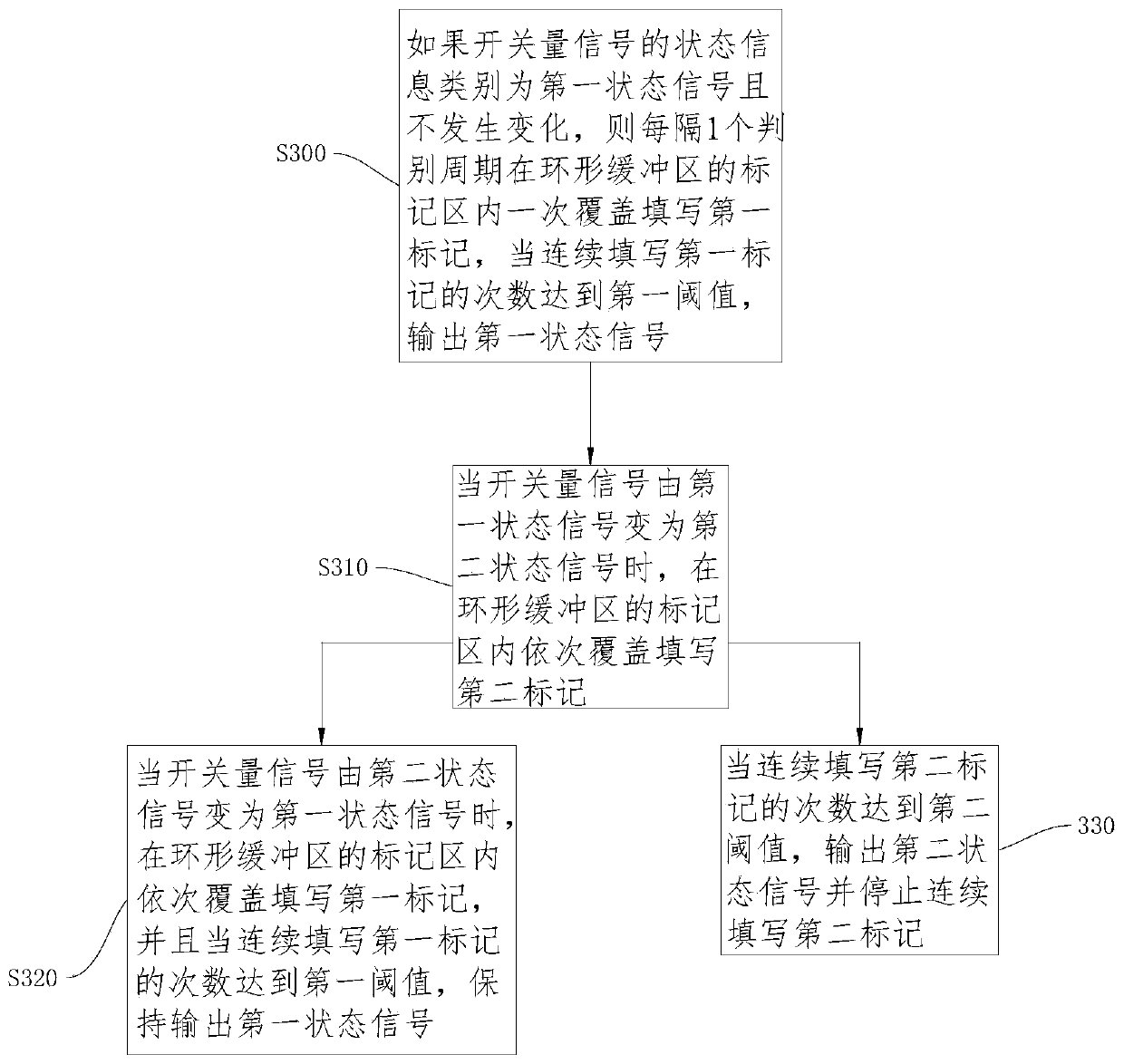
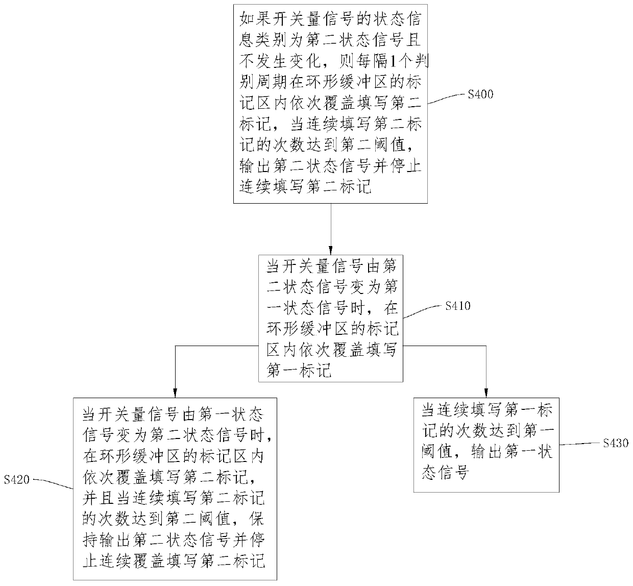
[0006] However, the switch signal anti-shake discrimination method in the existing structure or prior art has the following disadvantages: 1) It is impossible to perform anti-shake discrimination on multi-state switch information; 2) It is impossible to perform different anti-shake parameters for each switch state 3) It is impossible to perform multi-threshold discrimination for each switch state

Method used


Image

  • Switch signal anti-shake discrimination method and switch signal anti-shake discrimination device
  • Switch signal anti-shake discrimination method and switch signal anti-shake discrimination device
  • Switch signal anti-shake discrimination method and switch signal anti-shake discrimination device

Examples


Embodiment Construction

[0046]In order to make the purpose, technical solutions and advantages of the embodiments of the present invention more clear, the technical solutions in the embodiments of the present invention will be clearly and completely described below in conjunction with the drawings in the embodiments of the present invention. Apparently, the described embodiments are some, but not all, embodiments of the present invention. The components of the embodiments of the invention generally described and illustrated in the figures herein may be arranged and designed in a variety of different configurations.

[0047] Accordingly, the following detailed description of the embodiments of the invention provided in the accompanying drawings is not intended to limit the scope of the claimed invention, but merely represents selected embodiments of the invention. Based on the embodiments of the present invention, all other embodiments obtained by persons of ordinary skill in the art without creative ...


PUM


Abstract

The invention discloses an anti-jitter distinguishing method and device of a switching value signal, and relates to the technical field of vehicles. The method comprises the steps that the switching value signal is received; the category of the state information of the switching value signal is judged; if it is judged that the switching value signal is in a first state according to the category ofthe state information of the switching value signal, first markers are overwritten in marking areas of an annular buffer zone in sequence, when the number of the times for writing the first markers reaches a first threshold, a first state signal is output; if it is judged that the switching value signal is in a second state according to the category of the state information of the switching valuesignal, second markers are overwritten in the marking areas of the annular buffer zone in sequence, when the number of the times for writing the second markers reaches a second threshold, a second state signal is output, and the second markers stop from being continuously written. The annular buffer zone is provided with the marking areas, and the marking areas are arranged in a ring. The anti-jitter distinguishing method of the switching value signal can be used in the anti-jitter distinguishing device of the switching value signal. By means of the method and the device, the multi-state switching value signal can be subjected to anti-jitter processing.

Description

technical field [0001] The invention relates to the technical field of automotive electronic signal detection, in particular to a method for judging anti-shake of a switch signal and a device for judging an anti-shake of a switch signal. Background technique [0002] As a trigger signal, the switch signal mainly monitors the working condition or working state of the automobile control system, and provides a signal to the ECU (automotive electronic integration) to respond when the working condition or state changes. Switching signals are mainly divided into positive trigger signals and negative trigger signals. The positive trigger signal transmits the positive voltage (high level signal) of the car power supply to the ECU through the switch, such as the gear switch signal, the brake switch signal, the power steering switch signal, and the air conditioner control power switch signal; on the contrary, the negative trigger signal is Use the switch to transmit the negative pole...

Claims


Application Information

Patent Timeline
Patent Type & Authority Patents(China)
IPC IPC(8): G05B23/02
CPCG05B23/0213
Inventor 杨栋
Owner HUNAN SANY INTELLIGENT CONTROL EQUIP
Why Eureka
Try Eureka