Full-automatic substrate cleaning machine

A cleaning machine, fully automatic technology, applied in the direction of steam flow control, electrostatic effect separation, solid separation, etc., can solve the problem of removing dust and debris on the surface of the substrate, unable to accurately reflect the production status of the product, and increase the number of artificial collision products. and other problems to achieve the effect of thorough cleaning and dust removal

Inactive Publication Date: 2016-10-26
上海功源电子科技有限公司
View PDF0 Cites 0 Cited by
  • Summary
  • Abstract
  • Description
  • Claims
  • Application Information

AI Technical Summary

Problems solved by technology

[0004] However, the traditional dust removal method is that the operator takes the substrate out of the material box by hand, and then places it on the dust blowing table for dust removal.
Using this method, on the one hand, the static electricity on the human body, sweat stains, dust, and body fluids on the hands are likely to affect the substrate and new products; on the other hand, manual contact inevitably increases the chance of artificially damaging the product; In the way of the substrate, most areas on the substrate bend and sag due to gravity, and the chips and bonding wires on the surface will be pulled to varying degrees, resulting in deformation of the bonding state of the chips and bonding wires
This kind of deformation occurs precisely during the transfer process of the strip, therefore, the subsequent detection will not accurately reflect the actual production situation of the product, and the adjustment of technicians and production equipment will produce wrong guidance
In addition, simple air blowing and dust removal cannot remove the dust and debris on the surface of the substrate as much as possible. Electrostatic dust removal greatly reduces the adhesion of dust and debris on the surface of the substrate through the action of electrostatic ions, and then removes the dust and debris on the surface as much as possible by blowing air. debris

Method used


Image

  • Full-automatic substrate cleaning machine

Examples


Embodiment Construction

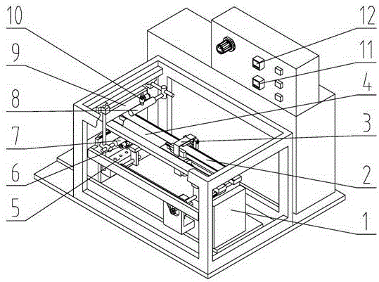
[0019] Attached below figure 1 The present invention is described in further detail with the specific embodiment:

[0020] Depend on figure 1 It can be seen that the present invention includes: base 1, front and rear guide rails 2, pneumatic gripper 3, base plate 4, lower electrostatic wind bar 5, lower blowing nozzle pressure regulating valve 6, lower blowing nozzle 7, upper blowing nozzle 8, upper electrostatic Wind rod 9, upper air blowing nozzle pressure regulating valve 10, air blowing low pressure stop pressure switch 11, air blowing recovery pressure switch 12.

[0021] Working process of the present invention is as follows:

[0022] 1. The pneumatic gripper 3 moves left along the front and rear guide rails 2 and closes, grabs the substrate 4 and moves right to the set position, the lower electrostatic air bar 5, the lower air blowing nozzle 7, the upper air blowing nozzle 8, and the upper electrostatic air bar 9 Open at the same time, blowing air to clean and remove...


PUM


Abstract

A full-automatic substrate cleaning machine comprises a pedestal, front and rear guide rails, a pneumatic gripper, a substrate, a lower static blower bar, a lower blow nozzle pressure regulating valve, a lower blow nozzle, an upper blow nozzle, an upper static blower bar, an upper blow nozzle pressure regulating valve, a blow low-pressure stop pressure switch and a blow recovery pressure switch. The invention has the following advantages: the static blower bars and the blow nozzles are used for repeatedly blowing the substrate simultaneously from upper and lower sides of the substrate to remove dust, thus making cleaning and dust removal to be more thorough; by low blow pressure, blow cleaning and dedusting are automatically stopped, and after blow pressure is recovered, cleaning air source pressure for blow cleaning and dedusting is automatically recovered, thus ensuring effectiveness of substrate cleaning and dedusting with the effective management; blow pressure at upper and lower sides of a material strip can be independently adjusted, thus keeping blow pressure at the upper and lower sides basically balanced and effectively realizing anti-shaking, anti-dropping and wear-resistant performance of the substrate.

Description

technical field [0001] The invention relates to an electrostatic dust removal for semiconductor wire bonding substrates and packaging substrates. Background technique [0002] In the semiconductor packaging industry, the purpose of die bonding is to place individual dies on leadframes or substrates (PCBs) and fix them with silver glue (epoxy). The lead frame or substrate provides a sticking position for the die (die pad), and is preset with extension feet or pads (pads) that can extend the circuit of the IC die. The purpose of the bonding wire is to connect the contacts on the die to the internal pins on the lead frame or substrate with a very thin gold wire (18~50um), so as to transmit the circuit signal of the IC die to the external bonding wire. The contact on the die is the first soldering point, and the contact on the inner pin is the second soldering point. First, sinter the end of the gold wire into a small ball, and then press-bond the small ball on the first solde...

Claims


Application Information

Patent Timeline
Patent Type & Authority Applications(China)
IPC IPC(8): B03C3/36
CPCB03C3/368
Inventor 卢冬青
Owner 上海功源电子科技有限公司
Why Eureka
Try Eureka