An ellipsoid portable ultrasonic transducer

An ultrasonic transducer, a portable technology, applied in the direction of fluid that utilizes vibration, etc., can solve the problems of embedded transducers that are inconvenient to move and carry, weak electric power capacity, and simple shape, so as to improve the ability to apply electric power and improve Active load, wide range of effects

Active Publication Date: 2021-02-02
杭州瑞利超声科技有限公司
View PDF8 Cites 0 Cited by
  • Summary
  • Abstract
  • Description
  • Claims
  • Application Information

AI Technical Summary

Problems solved by technology

Ordinary transducers and other embedded transducers need to be attached to a carrier such as a vibrating box before they can be put into the water, which is not conducive to the overall movement and portability of the device
[0003] In order to solve the shortcomings of the transducer, such as weak ability to apply electric power and inconvenient portability, domestic and foreign transducer experts have invented methods such as push-pull transducers by increasing the number of ceramic pieces, increasing the length of the tool head, and increasing the contact area with water. Transducers, etc., but these transducers need to be installed from top to bottom, which has obvious disadvantages such as loud noise and large space occupation, which is not conducive to home use or business people to carry
[0004] Whether it is an ultrasonic vibrating box composed of multiple vibrators, or an ultrasonic wand with a push-pull tool head, for household applications, there are significant shortcomings such as high noise, large volume, and not compact and beautiful appearance.
Embedded transducers have the disadvantage of being inconvenient to move and carry
[0005] In order to solve the problem of transducer immersion in water, some products at home and abroad put ordinary longitudinal vibration transducers into water as appropriate watertight, but there are problems such as small active radiation surface, weak ability to apply electric power, no corrosion resistance, and simple appearance.

Method used


Image

  • An ellipsoid portable ultrasonic transducer

Examples


specific Embodiment approach

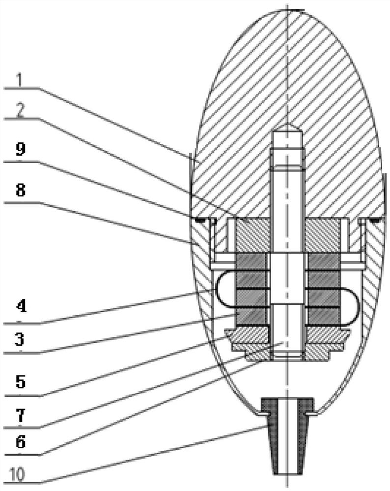
[0023] Step 1. Assembly of the transducer vibrator:

[0024] Fix the back cover nut 6, the back cover 5, the piezoelectric ceramic sheet 3, the electrode sheet 4, the front cover plate 2 and the screw rod 7 concentrically through a special fixture, and apply appropriate prestress in the vertical direction to ensure that the transducer structure is at a high It will not fall off during high-frequency and high-power vibration. There are four pairs of piezoelectric ceramic sheets 3 and electrode sheets 4, and the piezoelectric ceramic sheets 3 are electrically connected in parallel through the electrode sheets 4, that is, negative-positive, positive-negative, negative-positive, and positive-negative connections.

[0025] Step 2. Overall assembly of the transducer:

[0026] The vibrator of the transducer assembled in step 1 is connected with the ellipsoidal radiation head 1 through the protruding part of the screw 7 and tightened, thus forming the whole transducer.

[0027] Step...


PUM


Abstract

The invention discloses an ellipsoid-shaped portable ultrasonic transducer, which mainly includes an ellipsoid-shaped radiation head, etc., a front cover plate, a piezoelectric ceramic sheet, an electrode sheet, a back cover, and a back cover nut through a screw mechanically connected in series to form a transducer. The vibrator, the vibrator of the transducer is connected with the ellipsoidal radiation head through the protruding part of the screw to form the whole transducer. The sealing support connection, the connection between the ellipsoid shell and the watertight plug ensures its overall watertight characteristics, and the transducer as a whole is in contact with the water and radiates sound energy to it. The radiation head of the present invention uses an ellipsoid instead of a common cylinder or a circular table, and uses an ellipsoid as a whole to radiate instead of a plane or a cylinder, which can significantly increase the radiation surface of the transducer and improve the ability of the transducer to apply electric power; Into the water, which greatly reduces the noise radiated by the transducer through the water tank; it has the characteristics of cavitation corrosion resistance.

Description

technical field [0001] The invention relates to the technical field of ultrasonic transducers, in particular to an ellipsoidal portable ultrasonic transducer. Background technique [0002] The longitudinal vibration type ultrasonic cleaning transducer widely used at present has the remarkable characteristics of simple structure, low cost, stable and reliable performance, etc. Ordinary transducers and other embedded transducers need to be attached to a carrier such as a vibrating box before they can be put into the water, which has the disadvantage of being unfavorable for the overall movement and portability of the device. [0003] In order to solve the shortcomings of the transducer, such as weak ability to apply electric power and inconvenient portability, domestic and foreign transducer experts have invented methods such as push-pull transducers by increasing the number of ceramic pieces, increasing the length of the tool head, and increasing the contact area with water. ...

Claims


Application Information

Patent Timeline
Patent Type & Authority Patents(China)
IPC IPC(8): B06B1/06
CPCB06B1/06B06B2201/55
Inventor 刘文静金杭超刘细宝
Owner 杭州瑞利超声科技有限公司
Why Eureka
Try Eureka