A staple removal device and method of use thereof

A technology for dismantling devices and staples, applied in the direction of nail pullers, manufacturing tools, etc., can solve the problem that staples are not easy to disassemble, and achieve the effect of convenient and quick use

Active Publication Date: 2021-12-10
ANHUI POLYTECHNIC UNIV MECHANICAL & ELECTRICAL COLLEGE
View PDF8 Cites 0 Cited by
  • Summary
  • Abstract
  • Description
  • Claims
  • Application Information

AI Technical Summary

Problems solved by technology

[0003] Aiming at the deficiencies in the prior art, the purpose of the present invention is to provide a staple removal device with simple structure and easy use, which is used to solve the problem that the staples are not easy to disassemble in the prior art; the present invention also provides the How to use the staple removal device

Method used


Image

  • A staple removal device and method of use thereof
  • A staple removal device and method of use thereof

Examples


Embodiment Construction

[0026] In the present invention, it should be understood that the terms "length", "width", "upper", "lower", "front", "rear", "left", "right", "vertical", "horizontal" ", "Top", "Bottom", "Inner", "Outer", "Clockwise", "Counterclockwise", "Axial", "Plane Direction", "Circumferential" and other indications are based on The orientation or positional relationship shown in the drawings is only for the convenience of describing the present invention and simplifying the description, and does not indicate or imply that the referred device or element must have a specific orientation, be constructed and operated in a specific orientation, and therefore cannot be understood as Limitations on the Invention.

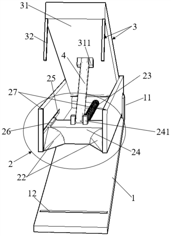
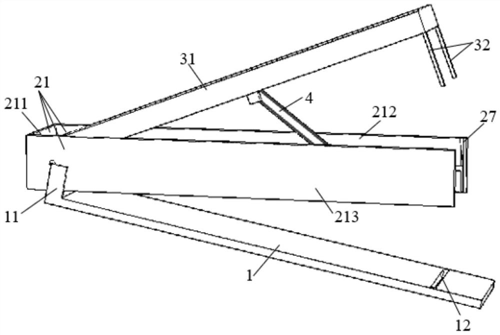
[0027] Such as figure 1 , figure 2 As shown, a staple removal device includes a base 1, a thimble mechanism 2 and a nail pushing mechanism 3, the thimble mechanism 2 includes a base 21, a cone thimble 22 and a spring 23, and one end of the base 1 is connected to the base through ...


PUM


Abstract

The invention discloses a staple removal device, comprising a base, a thimble mechanism and a nail pushing mechanism. The thimble mechanism includes a base, a vertebral body thimble and a spring. One end of the base is connected to the base through a bracket, and the base and the base can be connected relative rotation. The base includes plate I, plate II and plate III. Plate II and plate III are symmetrically arranged on both sides of plate I and are connected to plate I to form a U-shaped structure. One end of the spring is fixedly connected to plate I, and the other end of the spring is connected to plate I. One end is connected with the vertebral body thimble. The vertebral body thimble is connected with the spring through a connecting plate, one side of the connecting plate is connected with the spring, and the other side of the connecting plate is connected with the vertebral body thimble. The nail pushing mechanism includes a pressure plate, one end of the pressure plate is connected with the base through a rotating shaft, the pressure plate can be rotated relative to the base, and the end of the pressure plate away from the plate I is provided with a long strip thimble. The staple removal device also includes a connecting rod, one end of the connecting rod is connected with the connecting plate, and the other end of the connecting rod is connected with the pressing plate. The present invention also provides a method of using the staple removal device.

Description

technical field [0001] The invention belongs to the technical field of office equipment, and in particular relates to a staple removal device and a using method thereof. Background technique [0002] In the daily office, it is often encountered that the staples are removed from the bound document paper pages, and after adding or reducing the paper pages, they are bound again. The nail heads on both sides of the n-shaped staple are pressed into the document by the stapler. After the paper pages, a fixed part is formed on the front pages of the document, and two symmetrical bends are formed on the back pages of the document to prevent the pages from falling off. In removing the staples, especially in order not to make the documents When the paper page is lost, due to the high hardness of the staple, usually use the tip of a small knife or a tool with a cone to pry up the two elbows and then pry the staple out from the front of the document, slightly If you are careless or use...

Claims


Application Information

Patent Timeline
Patent Type & Authority Patents(China)
IPC IPC(8): B25C11/00
CPCB25C11/00
Inventor 束文强陈海锋李双州
Owner ANHUI POLYTECHNIC UNIV MECHANICAL & ELECTRICAL COLLEGE
Why Eureka
Try Eureka