
Wheel disc type flow splitting equipment and object flow splitting method

A shunting equipment and turntable technology, which is applied in the direction of conveyor objects, transportation and packaging, etc., can solve the problems of low shunting efficiency, high cost, and high efficiency, and achieve high shunting efficiency, good shunting effect, and simple structure.

Pending Publication Date: 2019-03-12
CHINA POST SCI & TECH
View PDF0 Cites 2 Cited by
  • Summary
  • Abstract
  • Description
  • Claims
  • Application Information

AI Technical Summary

Problems solved by technology

[0003] The cross-transplanting diversion method is only suitable for handling regular boxes, not suitable for handling special-shaped items and complicated packaging items, and only suitable for left and right two-way diversion, which has low efficiency
The balance wheel shunt is composed of several small units that can swing, and the cost is high
It is only suitable for processing regular boxes, not suitable for processing special-shaped items and complex packaging items, only suitable for left and right two-way diversion, high efficiency
[0004] Therefore, there is an urgent need for an article diversion device, which can solve the problem that the existing article diversion equipment is only suitable for left and right two-way diversion, the diversion efficiency is low, and it is impossible to divert and package complex and special-shaped items.

Method used


Image

  • Wheel disc type flow splitting equipment and object flow splitting method
  • Wheel disc type flow splitting equipment and object flow splitting method
  • Wheel disc type flow splitting equipment and object flow splitting method

Examples


Embodiment Construction

[0034] In order to make the technical problems solved by the present invention, the technical solutions adopted and the technical effects achieved clearer, the technical solutions of the embodiments of the present invention will be further described in detail below in conjunction with the accompanying drawings. Obviously, the described embodiments are only the technical solutions of the present invention. Some, but not all, embodiments. Based on the embodiments of the present invention, all other embodiments obtained by those skilled in the art without making creative efforts belong to the protection scope of the present invention.

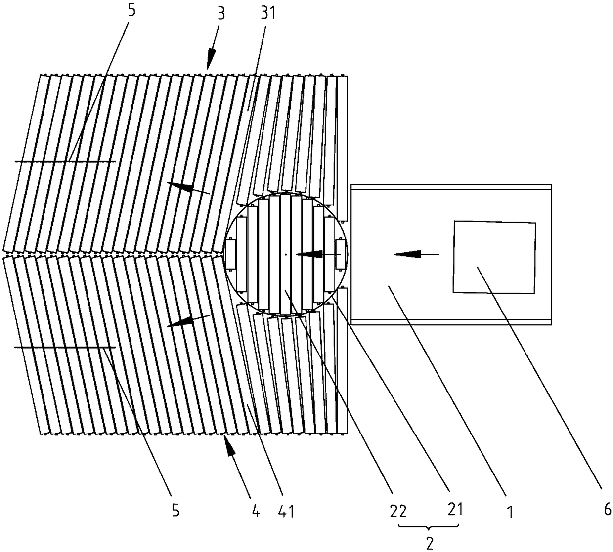
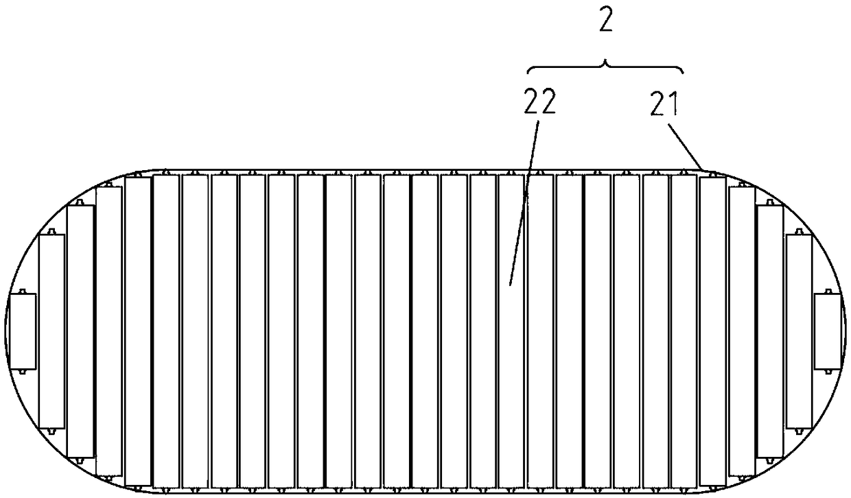
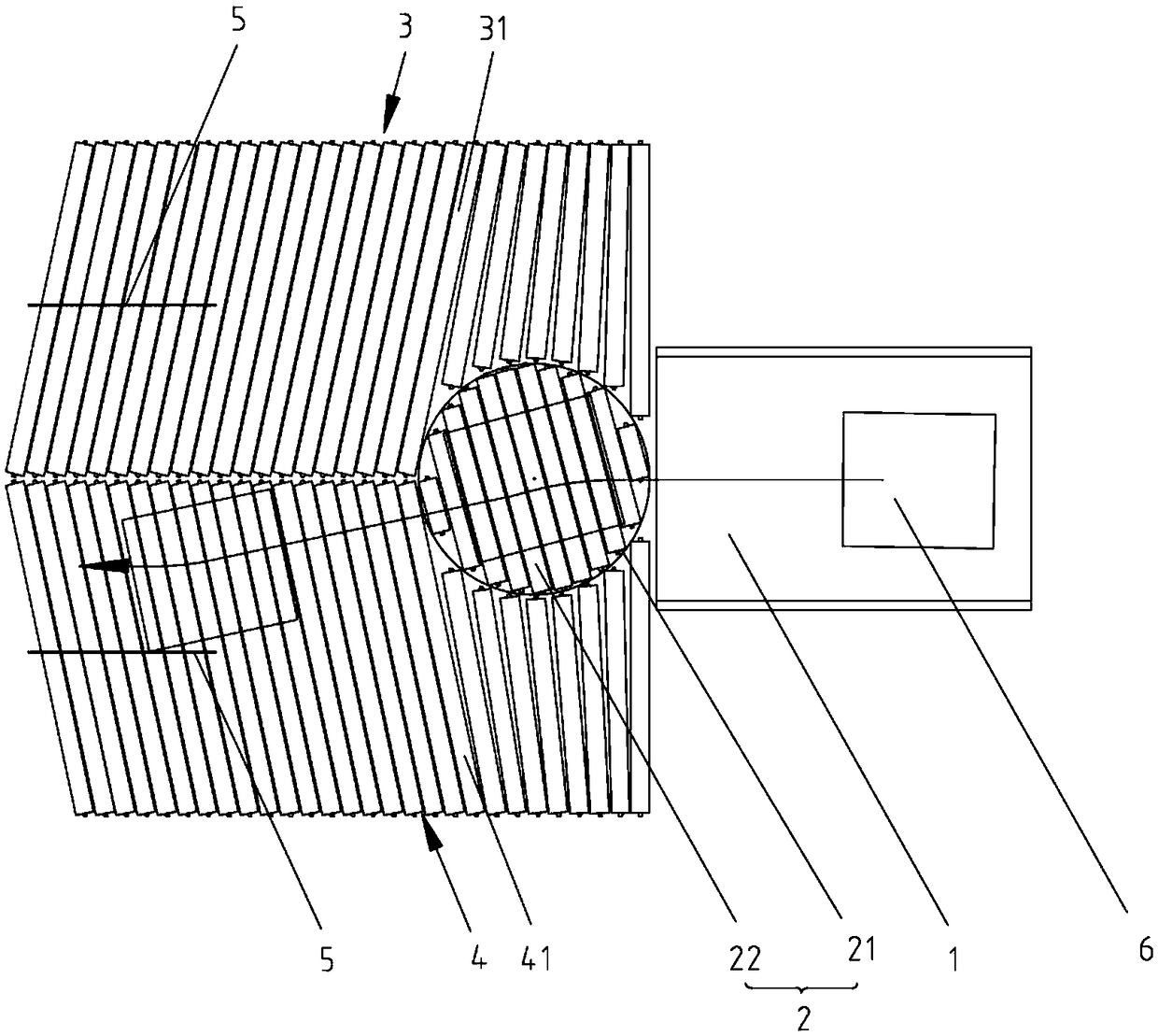
[0035] This embodiment provides a turntable type diverting device, which has a simple structure and low cost, can realize multi-way diversion, and has high diversion efficiency. It can not only divert regular items, but also divert irregularly shaped items with complex shapes and packages. This embodiment is described by taking the division into 4...


PUM


Abstract

The invention discloses wheel disc type flow splitting equipment and an object flow splitting method and belongs to the technical field of logistics sorting. The equipment comprises a conveying device, a horizontal roller turnplate, a left oblique roller set and a right oblique roller set, wherein the conveying device is used for conveying objects; the horizontal roller turnplate is used for receiving the objects conveyed by the conveying device and comprises a first roller set, the first roller set comprises a plurality of parallel first rollers which are arranged in the turnplate and rotatesynchronously around self axes correspondingly, the objects are deviated after the turnplate rotates by an angle, and preliminary flow splitting is achieved; and the left oblique roller set and the right oblique roller set are used for receiving the objects conveyed by the roller turnplate, the left oblique roller set comprises a plurality of parallel left oblique rollers rotating synchronously around self axes correspondingly, the right oblique roller set comprises a plurality of parallel right oblique rollers rotating synchronously around self axes correspondingly, an obtuse angle is formedbetween the arranging directions of the multiple left oblique rollers and the multiple right oblique rollers and the conveying direction of the conveying device, the objects can be continuously conveyed outwards, and flow splitting is better achieved. The equipment and method can be used for achieving multi-path flow splitting, and flow splitting and sorting can be performed on special-shaped objects.

Description

technical field [0001] The invention relates to the technical field of material flow sorting, in particular to a turntable type flow distribution device and a method for using the device to carry out object distribution. Background technique [0002] With the rapid development of the express delivery industry, the processing volume of express delivery items has increased rapidly, and the market demand for automatic distribution (shunt) equipment in the logistics industry is increasing. At present, the cross-transplanting method and the balance wheel shunt method are mostly used for article shunting. [0003] The cross transplanting and shunting method is only suitable for handling regular boxes, not suitable for handling special-shaped items and complicated packaging items, and only suitable for left and right two-way shunting, which has low efficiency. The balance wheel shunt is composed of several small units that can swing, and the cost is high. It is only suitable for ...

Claims


Application Information

Patent Timeline
IPC IPC(8): B65G47/71
CPCB65G47/71
Inventor 代铁山李存禹谢博峰周鹤丁一夫
Owner CHINA POST SCI & TECH
Learn More