Thread take-up mechanism used for sewing machine and sewing machine

A sewing machine and thread take-up lever technology, applied in the field of sewing machines, can solve the problems of difficult thread-take-up time and thread-take-up stroke adjustment, and achieve the effect of reducing the rotation frequency

Inactive Publication Date: 2019-03-12
JACK SEWING MASCH CO LTD
View PDF6 Cites 2 Cited by
  • Summary
  • Abstract
  • Description
  • Claims
  • Application Information

AI Technical Summary

Problems solved by technology

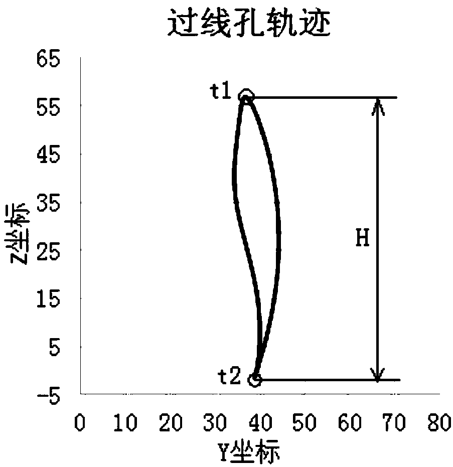
[0004] When the sewing machine uses rotary hooks of different sizes, the thread take-up stroke needs to be adjusted accordingly. In the existing sewing machines, the size parameters of the thread take-up mechanism are all fixed values, so it is difficult to realize the adjustment of the thread take-up time and the thread take-up stroke. Therefore, a thread take-up mechanism with adjustable thread take-up time and thread take-up stroke is required

Method used


Image

  • Thread take-up mechanism used for sewing machine and sewing machine
  • Thread take-up mechanism used for sewing machine and sewing machine
  • Thread take-up mechanism used for sewing machine and sewing machine

Examples


Embodiment Construction

[0038] The implementation of the present invention will be illustrated by specific specific examples below, and those skilled in the art can easily understand other advantages and effects of the present invention from the contents disclosed in this specification.

[0039] see Figure 1 to Figure 11 . It should be noted that the structures, proportions, sizes, etc. shown in the drawings attached to this specification are only used to match the content disclosed in the specification, for those who are familiar with this technology to understand and read, and are not used to limit the implementation of the present invention. Limiting conditions, so there is no technical substantive meaning, any modification of structure, change of proportional relationship or adjustment of size, without affecting the effect and purpose of the present invention, should still fall within the scope of the present invention. within the scope covered by the disclosed technical content. At the same t...


PUM


Abstract

The invention provides a thread take-up mechanism used for a sewing machine and the sewing machine. The thread take-up mechanism includes a thread take-up rod, a connecting rod assembly and a fixedlyarranged driving part; one end of the thread take-up rod is rotatably arranged, the other end of the thread take-up rod is provided with a thread through hole, one end of the connecting rod assembly is connected with the driving part, the other end of the connecting rod assembly is connected with the thread take-up rod, and the driving part drives the connecting rod assembly to swing in a reciprocating mode. The connecting rod assembly has three states, the connecting rod assembly in the first state and the connecting rod assembly in the second state are symmetrically arranged on the two sidesof the connecting rod assembly in the third state, the connecting rod assembly is in a straight line state in the third state, the thread through hole of the thread take-up rod is located at the highest point in the first state and the second state, and the thread through hole of the thread take-up rod is located at the lowest point in the third state. According to the mechanism and the sewing machine, the driving part rotates once, the thread through hole of the thread take-up rod can be at the highest point twice, and the rotation frequency of the driving part is reduced.

Description

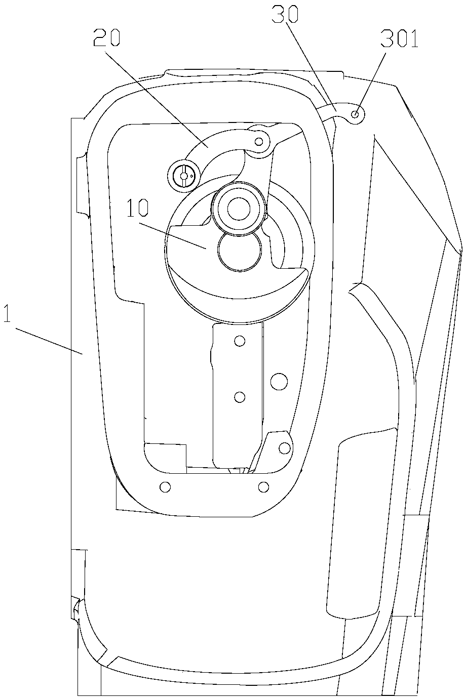
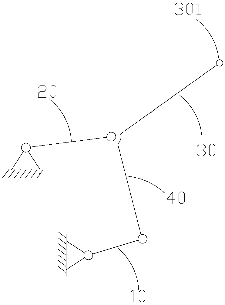
technical field [0001] The invention relates to the technical field of sewing machines, in particular to a thread take-up mechanism for sewing machines and the sewing machine. Background technique [0002] A sewing machine is exactly a machine that sews sewing materials by sutures, including a needle bar mechanism, a thread take-up mechanism, a feeding mechanism, a thread hook mechanism, a pressing mechanism, and a thread clamping device. The thread take-up and passing mechanism is to guide and transport the suture on the thread reel to the sewing needle, and cooperate with the needle bar mechanism to feed the suture. [0003] Existing sewing machine, head 1 is provided with thread take-up mechanism, see figure 1 and figure 2 As shown, the thread take-up mechanism generally includes: a thread take-up lever 30 and a thread take-up crank 40. The thread take-up lever 30 is provided with a thread passing hole 301 through which sutures can pass. One end of the thread taking-up...

Claims


Application Information

Patent Timeline
Patent Type & Authority Applications(China)
IPC IPC(8): D05B49/00D05B69/10
CPCD05B49/00D05B69/10
Inventor 郑吉祝书伟位延辉
Owner JACK SEWING MASCH CO LTD
Why Eureka
Try Eureka