
Floating head heat exchanger with dual-seal

A double seal and heat exchanger technology, applied in the direction of heat exchanger types, indirect heat exchangers, heat exchanger sealing devices, etc., can solve the problems of fluid cross contamination, fluid contamination, affecting subsequent use of fluids, etc., to achieve improved sealing Effect, prevention of mixed contamination, effect of reducing the probability of leakage

Pending Publication Date: 2019-03-12
金冬梅
View PDF10 Cites 0 Cited by
  • Summary
  • Abstract
  • Description
  • Claims
  • Application Information

AI Technical Summary

Problems solved by technology

[0004] The invention provides a double-sealed floating head heat exchanger, which has the advantages of good sealing effect at the floating head heat exchanger and the advantages of being convenient for external operators to know whether the floating head is leaking in time, and solves the problems of the existing floating head heat exchanger. It is sealed with the floating tube sheet by the floating head gasket. During the use of the floating head heat exchanger, the floating head gasket may be damaged due to factors such as medium and temperature, resulting in the leakage of the fluid inside the tube bundle, thereby affecting the heat exchange fluid. Cause pollution, although some floating head heat exchangers adopt double sealing measures to improve the sealing effect of the floating head, which only reduces the probability of leakage. Since the floating head is located inside the shell, when a leak occurs at the floating head, external operators cannot know in time Leakage, leading to cross-contamination of heat exchange fluids, affecting the subsequent use of fluids

Method used


Image

  • Floating head heat exchanger with dual-seal
  • Floating head heat exchanger with dual-seal
  • Floating head heat exchanger with dual-seal

Examples


Embodiment Construction

[0024] The following will clearly and completely describe the technical solutions in the embodiments of the present invention with reference to the accompanying drawings in the embodiments of the present invention. Obviously, the described embodiments are only some, not all, embodiments of the present invention. Based on the embodiments of the present invention, all other embodiments obtained by persons of ordinary skill in the art without making creative efforts belong to the protection scope of the present invention.

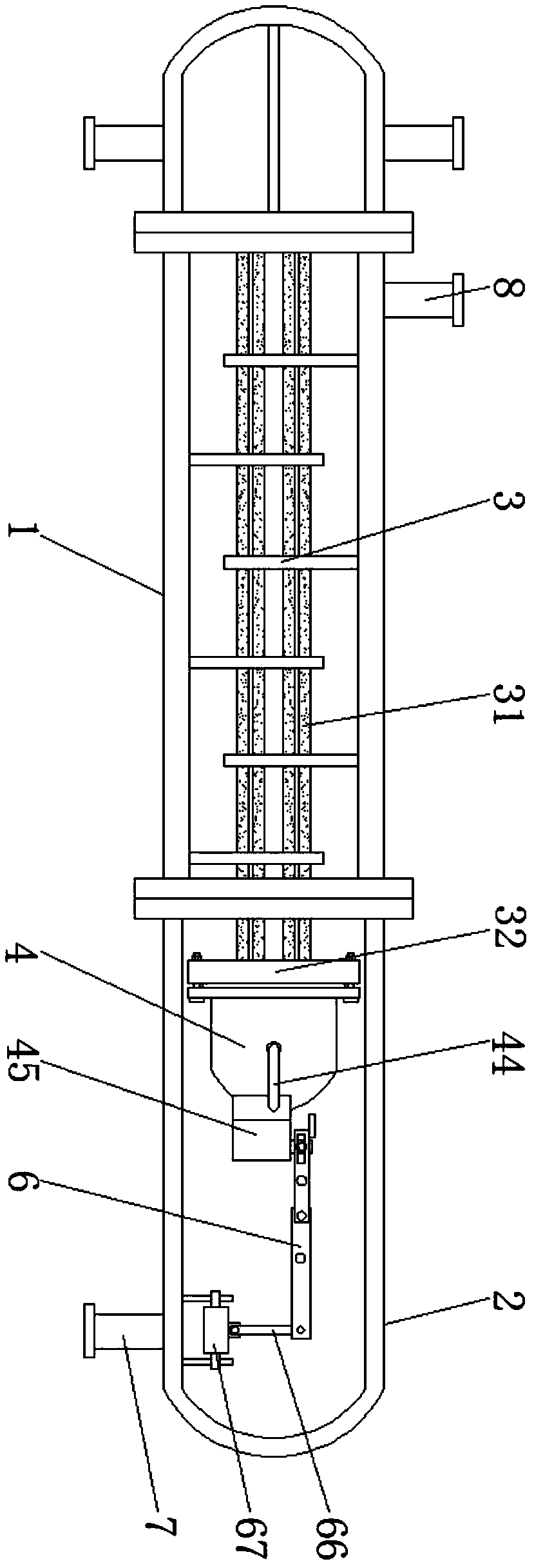
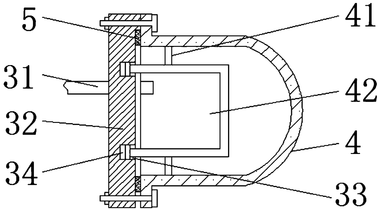
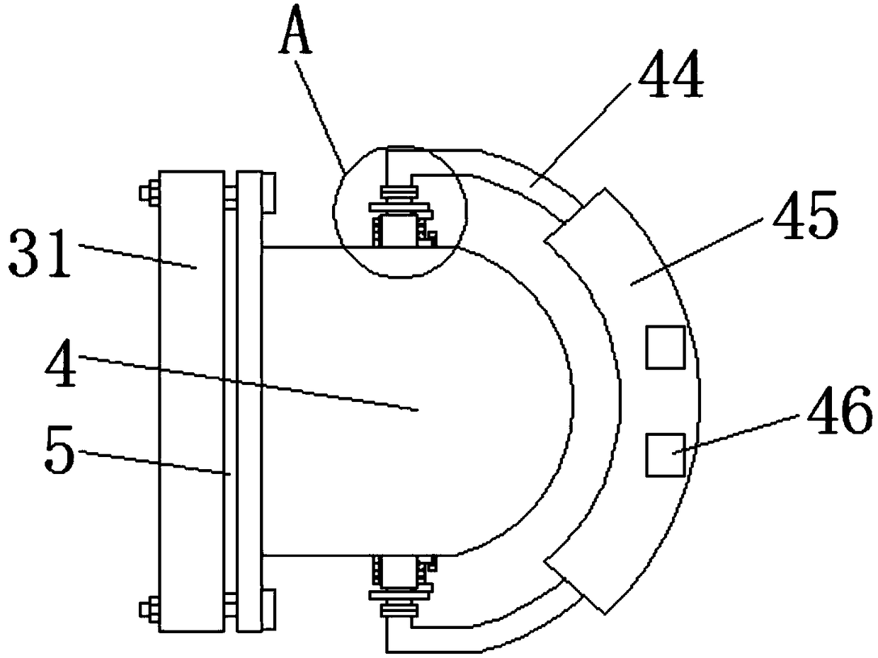
[0025] see Figure 1-6, a double-sealed floating head heat exchanger, including a large floating head 4 installed in the inner cavity of the shell 1 and the outer head cover 2 and a linkage device 6, the outer shell 1 and the outer head cover 2 are connected by a flange seal, and the inner cavity of the outer head cover 2 The distance between the front of the floating tube plate 32 and the front of the floating tube plate 32 is 6-10 cm. By reserving the space ...


PUM


Abstract

The invention relates to the technical field of heat exchange equipment, and discloses a floating head heat exchanger with dual-seal. The floating head heat exchanger comprises a large floating head and a linking device which are mounted in an inner cavity of a housing and an inner cavity of an outer head cover, wherein the housing is in sealing connection with the outer head cover through a flange; a baffle plate is movably arranged inside the housing in a sleeving mode; and the middle part of the baffle plate is fixedly equipped with a tube bundle in the sleeving mode. According to the floating head heat exchanger with dual-seal disclosed by the invention, through dual-isolating effect of the large floating head and a small floating head, the sealing effect of the tube bundle and the floating heads is improved; fluid in the tube bundle or the housing leaks to a position between the large floating head and the small floating head; and after fluid enters the box body, the box body moves downwards, so that a sealing plug blocks a flow tube, and leakage at the floating head inside the housing is determined according to great reduction of fluid flow at the flowing tube, and therefore,the equipment is switched off at the first time for maintaining, and two fluids for heat exchange are prevented from being mixed and polluted to affect follow-up use of fluid.

Description

technical field [0001] The invention relates to the technical field of heat exchange equipment, in particular to a double-sealed floating head heat exchanger. Background technique [0002] The heat exchanger is a device that transfers part of the heat of the hot fluid to the cold fluid. It is widely used in chemical, petroleum, power, food processing and other fields. The heat exchanger includes fixed tube-sheet heat exchangers and U-shaped tube-sheet heat exchangers. , Floating head heat exchanger, etc. Among them, the tube bundle of the floating head heat exchanger can be drawn out, which is easy to clean, and has the advantages of unlimited medium literature, so it is more widely used. [0003] However, in the existing floating head heat exchanger, the floating head and the floating tube sheet are sealed by the floating head gasket. During the use of the floating head heat exchanger, the floating head gasket may be damaged due to factors such as medium and temperature, re...

Claims


Application Information

Patent Timeline
IPC IPC(8): F28D7/16F28F11/00
CPCF28D7/16F28F11/00
Inventor 金冬梅
Owner 金冬梅
Learn More