
Electric kettle

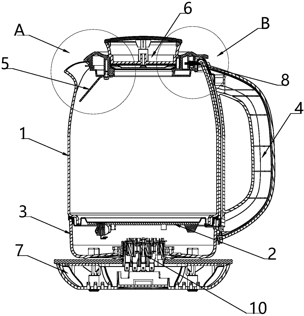
An electric kettle and lid technology, which is applied to water boiling utensils, overflow prevention, cooking utensils, etc., can solve the problems of small contact surface of air bubbles, increased foam, overflowing outside the kettle, etc., so as to prevent splashes and increase detection. area, the effect of improving accuracy

Inactive Publication Date: 2019-03-15
JOYOUNG CO LTD
View PDF11 Cites 2 Cited by
  • Summary
  • Abstract
  • Description
  • Claims
  • Application Information

AI Technical Summary

Problems solved by technology

[0007] However, the spout of an electric kettle is generally open, and during the heating process, steam or air bubbles will quickly gather and overflow toward the spout, and the installation position of the above-mentioned anti-overflow electrode is near the side of the handle, which cannot be easily It is better to quickly collect the foam formation of the spout, and quickly take anti-overflow measures, especially, when the water outlet edge of the spout is lower than the spout of the liner, it is easier to overflow from the spout
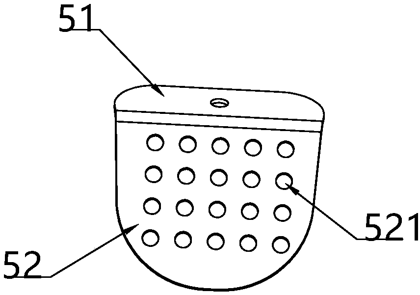
In addition, the anti-overflow electrode is generally set in a cylindrical shape, the contact surface of the bubbles is small, and the detection effect is not accurate enough
[0008] In addition, the patent application number CN201320276373.2 discloses a kettle lid with a filter, and the side of the lid facing the spout is provided with a filter for filtering during pouring, but this technical solution cannot achieve a good The anti-overflow effect, during the heating process, if there is no detection and control, the foam will continue to increase, overflowing the body of the pot, there is a safety risk

Method used


Image

  • Electric kettle
  • Electric kettle
  • Electric kettle

Examples


Embodiment 2

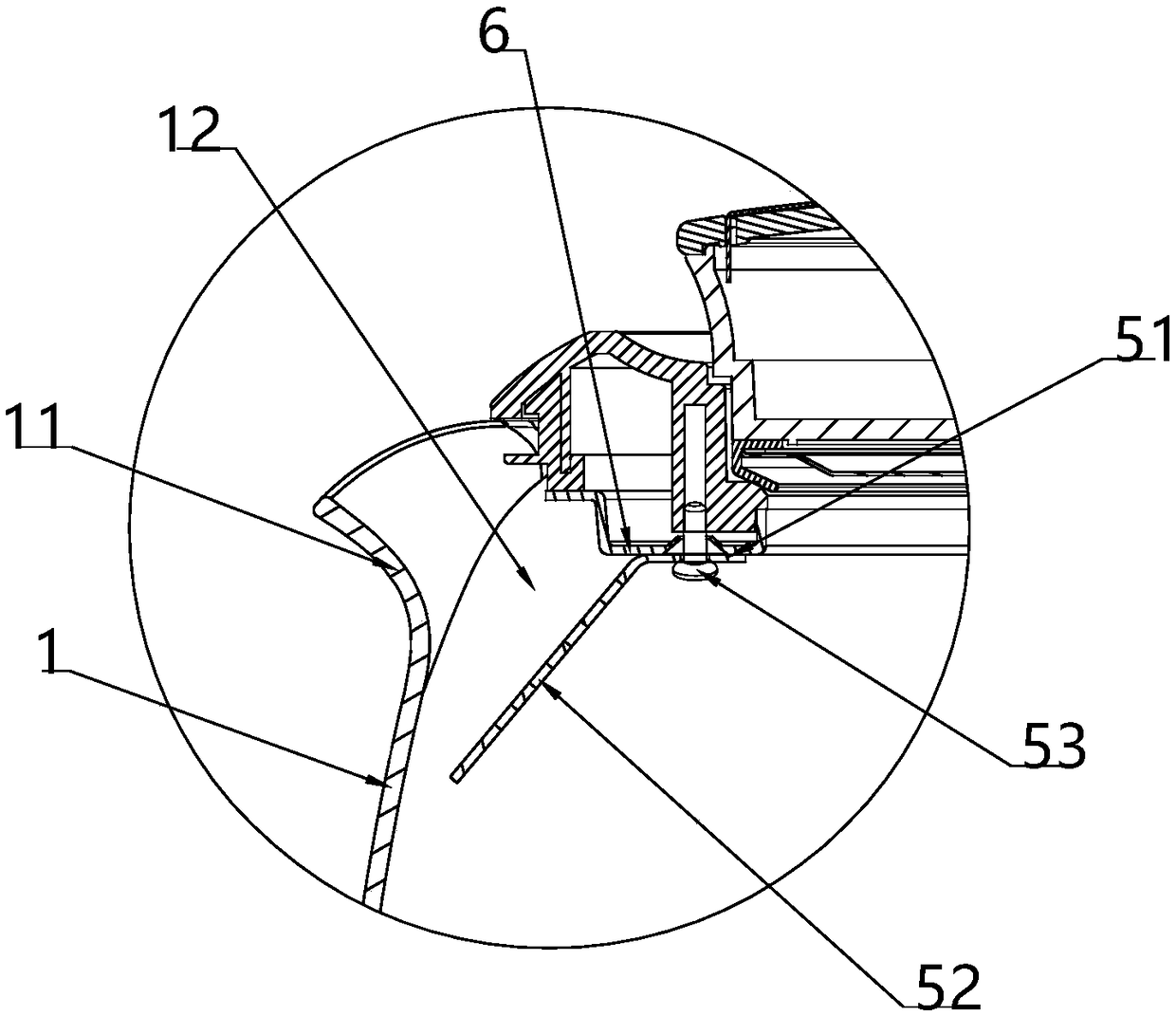
[0059] Based on the structure of Embodiment 1, when the pot cover 6 includes an upper cover 61 and a lower cover 62, and an accommodation chamber is formed between the upper cover 61 and the lower cover 62, the pot cover 6 and the overflow-proof electrode sheet 5, the second The installation scheme of a component 8 will be described in detail below in conjunction with the accompanying drawings in the present invention. The ways in which the anti-overflow electrode sheet 5 is connected with the kettle lid 6 are as follows:

[0060] The first type, such as image 3 As shown, the connection portion 51 of the anti-overflow electrode sheet 5 is located below the lower cover 62, and the anti-overflow electrode sheet 5 is connected to the lower cover 62 through a first fastener 53, the first The fastener 53 may be a structure such as a screw, a nut, or a bolt.

[0061] In the second type, the connecting portion 51 of the anti-overflow electrode sheet 5 is located between the upper ...

Embodiment 3

[0067] Based on the structure of embodiment 1 or 2, the mode that the first part 8 is connected with the pot lid 6 has the following several kinds:

[0068] First, the first component 8 is located between the upper cover 61 and the lower cover 62 , and the first component 8 can be connected to the upper cover 61 . For specific structural forms, reference may be made to the description below.

[0069]In order to ensure that the electrode signal can be stably transmitted to the control board, the first part 8 is elastically arranged on the pot cover 6, the first part 8 can slide in the pot cover 6, and the pot cover 6 is closed on the When the liner is put on, the first part 8 retracts into the pot lid 6 , and the first part 8 is in close contact with the second part 43 . That is, when the pot lid 6 is not installed, the length of the first component 8 protruding from the pot lid 6 is greater than the width of the pot lid 6 from the second component 43 . The above-mentioned fi...

Embodiment 4

[0077] Based on the structure of Embodiment 1 or 2 or 3, the second component 43 and the installation structure of the second component 43 on the handle 4 will be described in detail below.

[0078] like Figure 8 , Figure 9 As shown, the second part 43 is a sheet metal piece, one end of the metal piece is bent to form a first hooking part 431, and the first hooking part 431 is hooked at the spout of the inner container The part of the first hooking part 431 located in the inner container is in contact with the first component 8 (such as the above-mentioned conductive contact rod 81), and the other end of the metal part is electrically connected with the control board.

[0079] Further, the other end of the metal piece is connected to the handle 4 . At this time, the metal piece can also play the role of fixing the upper end of the handle 4 .

[0080] Further, the other end of the metal part is located between the outer wall of the inner container and the handle 4, and als...


PUM


Abstract

The invention provides an electric kettle. The electric kettle comprises a kettle body and a power source base. The kettle body comprises an inner container for containing liquid, a handle arranged onthe side of the inner container, a bottom cover arranged below the inner container and a kettle lid arranged on the upper portion of the inner container. An open spout is arranged on the inner container, the kettle lid and the inner container are detachably connected, an anti-overflowing electrode plate is arranged on the side, towards the spout, of the kettle lid and blocks a water outlet of thespout, and an electric connecting mounting base is further included, and comprises a first component and a second component. The first component is arranged on the kettle lid, the second component isarranged on the handle, the anti-overflowing electrode plate is electrically connected with the first component, and the second component is electrically connected with a control panel. According tothe technical scheme, the electric kettle is good in anti-overflowing effect and safe in use.

Description

technical field [0001] The invention relates to the field of household appliances, in particular to an electric kettle. Background technique [0002] The electric kettle is mainly used to heat the liquid as a drink. The main purpose of heating is to sterilize or obtain a more ideal taste. It often needs to be heated to boiling, and then poured out from the body of the electric kettle and wait for cooling before drinking or in the kettle. insulation. [0003] In addition, electric kettles are used to cook various ingredients in daily life, such as boiling water, noodles, scented tea, medicinal meals and tonics. Many ingredients take a long time to cook and are prone to overflow, which poses a safety risk. During the heating process of the beverage, the inside of the jug is relatively closed, and as the temperature rises, the liquid will evaporate into water vapor, which in turn will cause the pressure inside the jug to rise. When the electric kettle contains ingredients su...

Claims


Application Information

Patent Timeline
Patent Type & Authority Applications(China)
IPC IPC(8): A47J27/21A47J27/212A47J27/62
CPCA47J27/21008A47J27/21166A47J27/212A47J27/62
Inventor 朱泽春吴土荣刘宪明
Owner JOYOUNG CO LTD
Learn More