Automatic tire marking device

An automatic scribing and tire technology, applied to printing, typewriters, etc., can solve the problems of short service life, low production efficiency, waste, etc., and achieve the effect of reducing quality accidents, reducing labor intensity, and reducing cost expenditures

Active Publication Date: 2019-03-15
天津浩泰瑞森科技发展有限公司
View PDF9 Cites 1 Cited by
  • Summary
  • Abstract
  • Description
  • Claims
  • Application Information

AI Technical Summary

Problems solved by technology

[0003] The disadvantages of the above two scribing devices: 1. The color and position of the scribing are manually adjusted, and the efficiency of manual operation is low. It takes a long time to determine the color and position of the scribing. At this time, the tread is It is constantly advancing, so when the qualified product is obtained, the rubber material of the tread has been run out for a distance of 5-10 meters, and the rubber material of these unqualified products will become the returned rubber, re-milled or enter the extruder again, so that Increase production cost, low production efficiency
However, if it is directly put into the extruder and reused, it will face quality risks. The current design structure of the tread is mostly 2-4 compound rubber, and directly put into use will affect the formula ratio of the rubber in the corresponding structure of the tread.
2. When the tread operation is interrupted, the scribing rubber used will continue to flow, causing waste and polluting the environment
3. The rollers in the roller mechanism are vulnerable parts, and the metal rollers are expensive and have a short service life
4. Too much intervention by on-site operators will also lead to the risk of manual errors, and batch quality accidents are prone to occur

Method used


Image

  • Automatic tire marking device
  • Automatic tire marking device
  • Automatic tire marking device

Examples


Embodiment Construction

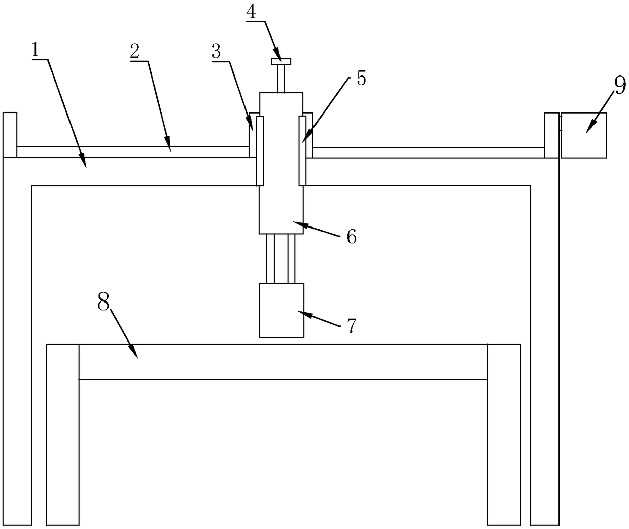
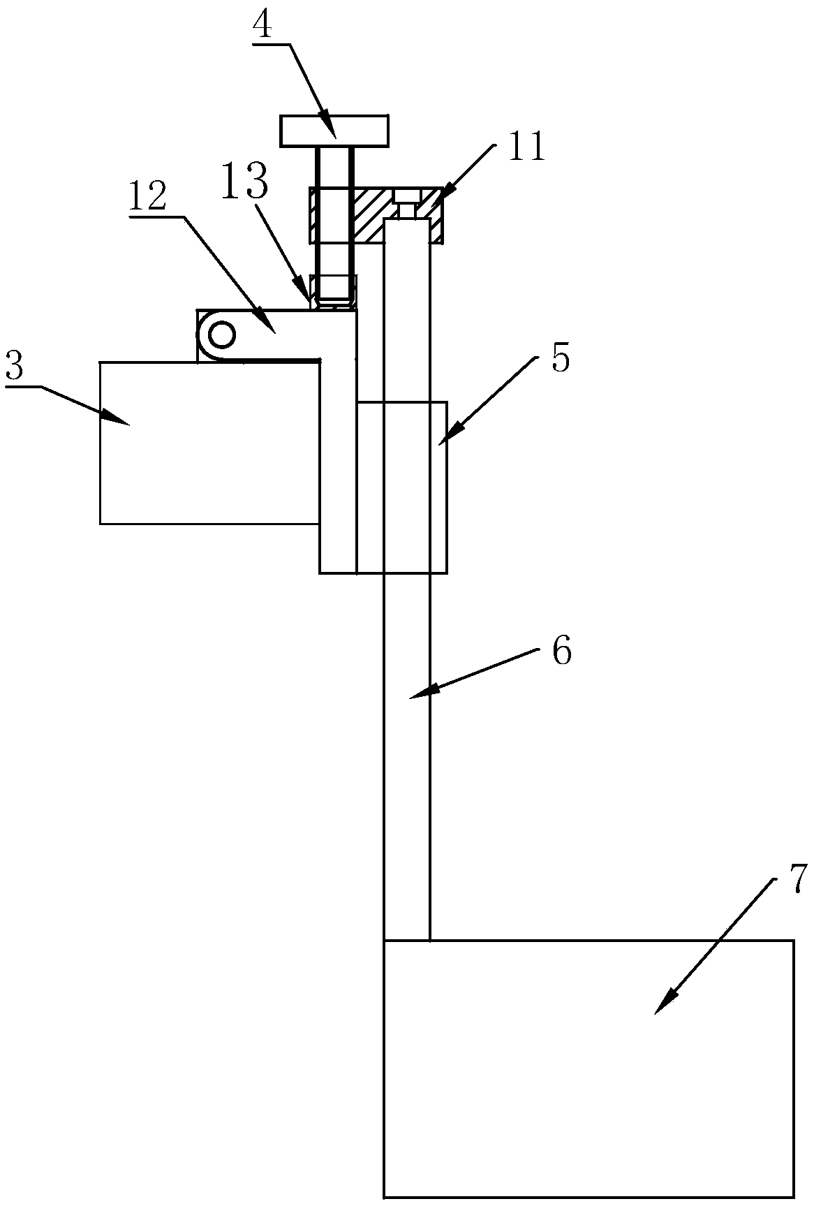
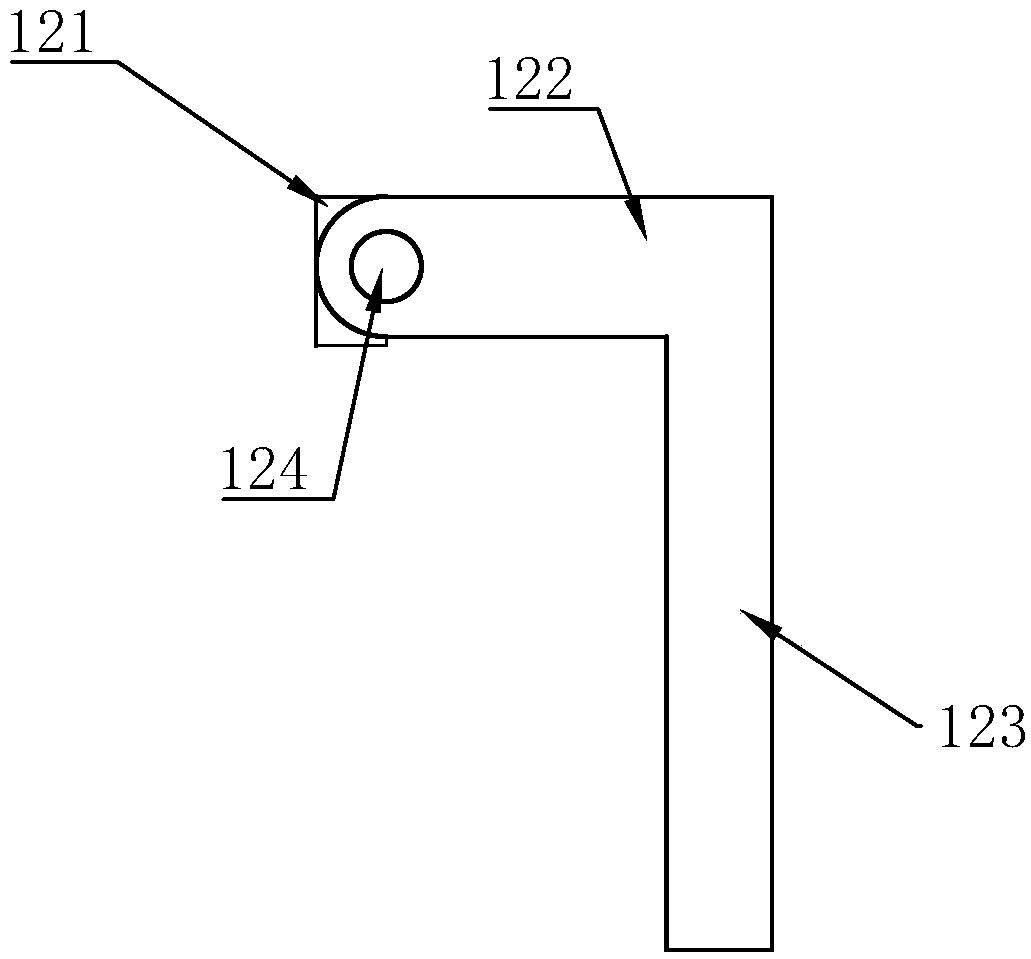
[0028] Such as Figure 1-Figure 4 As shown, an automatic tire scribing device of the present invention includes a transmission platform and multiple sets of scribing mechanisms equidistantly arranged on the transmission platform. There is a toothed belt assembly, the slider is connected with the stepper motor through the toothed belt assembly, one side of the anti-collision fixing assembly is connected to the slider for longitudinal rotation, and the other side of the anti-collision fixing assembly is provided with a vertical sliding relative to it. The large-character inkjet printer includes a large-character nozzle and an ink supply device. The large-character nozzle is connected to the ink supply device. The large-character nozzle is located above the transfer table and fixed to the output end of the cylinder.

[0029] Among them, each group of scribing mechanism only sprays the corresponding scribing color for the scribing position corresponding to one process. By setting ...


PUM


Abstract

The invention relates to an automatic tire marking device. The automatic tire marking device comprises a conveying table and a plurality of marking mechanisms arranged on the conveying table at equalintervals, each marking mechanism comprises a support, an anti-collision fixing assembly and a large-character ink-jet printer, a sliding rail is arranged on each support, a sliding block which horizontally slides along the corresponding sliding rail is arranged on each sliding rail, each sliding block is connected with a stepping motor through a tooth-shaped belt assembly, one side of each anti-collision fixing assembly is longitudinally and rotationally connected with the corresponding sliding block, the other side of each anti-collision fixing assembly is provided with an air cylinder whichslides vertically relative to the corresponding anti-collision fixing assembly, each large-character ink-jet printer comprises a large-character spray head and an ink supply device, the large-character spray heads are connected with the ink supply devices, the large-character spray heads are located above the conveying table and are fixed to the output ends of the air cylinders. According to theautomatic tire marking device, marking process intelligent manufacturing in the tire industry is realized, the marking beauty is improved, return rubber generated in the tire production pressing-out link is reduced, the energy consumption is reduced, the graded product rate is increased, the waste of the coating is reduced, the cost expenditure of easily damaged parts is reduced, the production efficiency is improved, the labor intensity is reduced, and the quality accidents are reduced.

Description

technical field [0001] The invention relates to the technical field of tire scribing, in particular to an automatic tire scribing device. Background technique [0002] The current market adopts two kinds of marking devices: one, the roller type, the color paste in the container is taken out by the roller and pressed on the tread. 2. Mark the needle and directly flow the color paste to the corresponding position of the tread. [0003] The disadvantages of the above two scribing devices: 1. The color and position of the scribing are manually adjusted, and the efficiency of manual operation is low. It takes a long time to determine the color and position of the scribing. At this time, the tread is It is constantly advancing, so when the qualified product is obtained, the rubber material of the tread has been run out for a distance of 5-10 meters, and the rubber material of these unqualified products will become the returned rubber, re-milled or enter the extruder again, so tha...

Claims


Application Information

Patent Timeline
Patent Type & Authority Applications(China)
IPC IPC(8): B41J3/407
CPCB41J3/407
Inventor 常俊环
Owner 天津浩泰瑞森科技发展有限公司
Why Eureka
Try Eureka