Frame structure formwork, assembled and spliced frame structure formwork and stereo frame structure formwork thereof

A frame structure and frame formwork technology, applied in the direction of formwork/formwork/work frame, formwork/formwork/work frame connector, building structure, etc., can solve the problems of low construction efficiency, high cost, complex structure, etc.

Active Publication Date: 2019-03-15
朱宏宇
View PDF7 Cites 0 Cited by
  • Summary
  • Abstract
  • Description
  • Claims
  • Application Information

AI Technical Summary

Problems solved by technology

[0004] The purpose of the present invention is to provide a frame mold, assembled frame structure and three-dimensional frame mold, to solve the technical problems of traditional formwork system structure complex, low construction efficiency, and high cost; and solve the problem of improving transportation efficiency and component recycling rate problem

Method used


Image

  • Frame structure formwork, assembled and spliced frame structure formwork and stereo frame structure formwork thereof
  • Frame structure formwork, assembled and spliced frame structure formwork and stereo frame structure formwork thereof
  • Frame structure formwork, assembled and spliced frame structure formwork and stereo frame structure formwork thereof

Examples


Embodiment 1

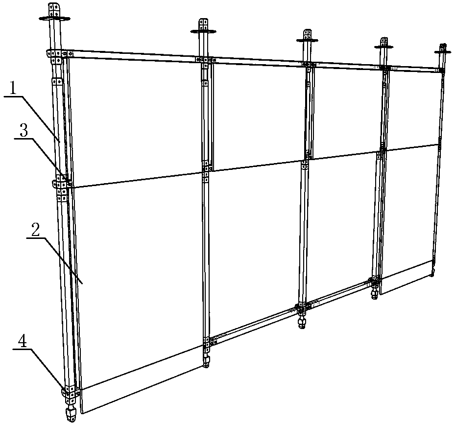
[0039] Embodiment one sees figure 1 , figure 2 As shown in the frame mold, the frame mold is composed of a frame mold 1 and a plate mold 2; the plate mold is detachably embedded in the frame opening of the frame mold. In this example, the frame molding is a facade frame molding.

[0040] see image 3 As shown, the frame mold 1 is a rectangular frame formed by two pairs of parallel main pipes connected vertically with shape joints; in this example, the frame mold 1 is a facade frame mold, which consists of a pair of vertical main pipes and a A rectangular frame formed by connecting horizontal main pipes with geometric nodes.

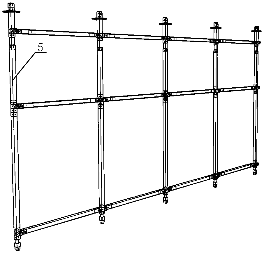
[0041] see Figure 4 As shown, the upper and lower ends of the vertical main pipe are inserted with vertical pin tubes 51; The external joint of the surface frame molding; the vertical pin tube inserted and fixed in the vertical main pipe forms the height adjustment pipe of the vertical main pipe; the frame molding forms a height-adjustable mold fra...

Embodiment 2

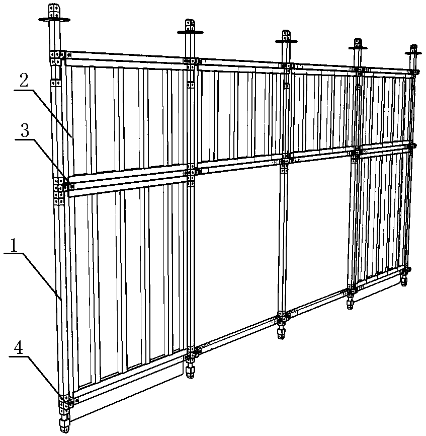
[0045] Embodiment two see Image 6 As shown, different from Embodiment 1, the frame mold in this example is a plane frame mold;

[0046] see Figure 7 As shown, the frame mold 1 is a planar frame mold, which is a rectangular frame formed by connecting a pair of vertical and horizontal main pipes and a pair of horizontal and horizontal main pipes by joints.

[0047] see Figure 8 As shown, the two ends of the horizontal main pipe are inserted with horizontal pin tubes 52; the horizontal pin tubes are correspondingly connected to the horizontal pipe joints of the shape joints; other horizontal pipe joints of the shape joints form the plane frame mold An external joint; a horizontal pin pipe inserted and fixed in the horizontal main pipe forms a length adjustment pipe of the horizontal main pipe; the frame mold forms a mold frame with adjustable length or width.

[0048] see Figure 9 As shown, the formwork 2 is a planar formwork; the outer surface of the formwork is provided w...


PUM


Abstract

Provided are a frame structure formwork, an assembled and spliced frame structure formwork and a stereo frame structure formwork thereof. The frame structure formwork is composed of a frame formwork and a board formwork through assembly. The frame formwork is a rectangular frame formed by vertically connecting two pairs of parallel main pipes through shape and position joints, the board formwork comprises form boards, the outer surface of each form board is provided with a pair of parallel fastening frames, and the board formwork is detachably embedded and fixed in a frame opening of the frameformwork. A frame framework is formed by sequentially splicing frame structure formworks transversely and vertically. Pipe fittings in the frame structure formwork have universality, vertical pipes and transverse pipes are both formed by main pipes identical in cross section size, meanwhile main pipes different in length and size are made to form a series of pipe fittings, and convenience is provided for machining and use. The frame structure formwork can be widely applied to a concrete pouring formwork system.

Description

technical field [0001] The invention relates to the field of building construction, in particular to a construction formwork. Background technique [0002] At present, for general building structures, integral cast-in-place construction has well-known performance advantages and is an irreplaceable basic construction mode, especially cast-in-place concrete construction has achieved efficient and economical mechanized construction; while prefabricated component construction only A local replacement process that can be constructed by the cast-in-place method is determined by the nature of the concrete material; a reasonable choice of cast-in-place and prefabrication to achieve complementary advantages is an important issue faced by concrete structure construction. [0003] The most difficult problem to solve in cast-in-place concrete construction is the formwork project. Improving the equipment composition and construction mode of the formwork to realize the assembly constructi...

Claims


Application Information

Patent Timeline
Patent Type & Authority Applications(China)
IPC IPC(8): E04G11/02E04G11/08E04G11/38E04G11/48E04G17/00
CPCE04G11/02E04G11/08E04G11/38E04G11/48E04G17/00E04G2017/008
Inventor 朱宏宇
Owner 朱宏宇
Why Eureka
Try Eureka