A compression and recovery air pump

A technology for compressing air and air pumps, which is applied to pumps, piston pumps, and liquid variable displacement machinery, etc. It can solve the problems of no compressed air and low efficiency of electric energy conversion to air energy, and achieve the effect of reducing costs

Inactive Publication Date: 2018-03-27
张谭伟
View PDF5 Cites 0 Cited by
  • Summary
  • Abstract
  • Description
  • Claims
  • Application Information

AI Technical Summary

Problems solved by technology

[0002] Air compressors are indispensable air source equipment for industrial enterprises, and are widely used in air source equipment for pneumatic tools in various industries (traditional air power: air motors, pneumatic tools, rock drills, pneumatic picks, pneumatic wrenches, pneumatic sandblasting, Instrument control and automation devices, tool replacement in machining centers, vehicle braking, opening and closing of doors and windows, blowing weft yarns with compressed air in air-jet looms instead of shuttles, food and pharmaceutical industries, using compressed air to stir slurry, starting large marine diesel engines, Wind tunnel experiments, underground channel ventilation, metal smelting, oil well fracturing, high-pressure air blasting coal mining, weapon systems, missile launches, torpedo launches, submarine ups and downs, shipwreck salvage, seabed oil exploration, hovercraft, tire inflation), etc., but everyone We all know that compressed air is very inefficient in converting electrical energy into air energy. At present, there is no recovery technology for compressed air at home and abroad.

Method used


Image

  • A compression and recovery air pump
  • A compression and recovery air pump
  • A compression and recovery air pump

Examples


Embodiment

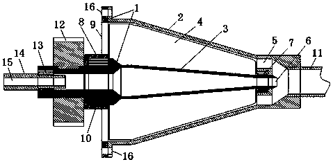
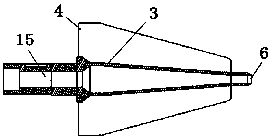
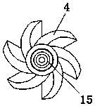
[0024] refer to Figure 1-Figure 7 , the compression and recovery air pump 1 of the present embodiment includes a pump casing 2 and a pump core 3, the pump core 3 includes a mandrel, the mandrel is a hollow mandrel, the front end is a return air inlet 15, and the rear end It is the return air exhaust port 6, and the mandrel is provided with a turbine blade 4; the pump housing 2 includes a housing and a cover plate 8, and the cover plate 8 is fixedly connected with the housing, and the cover plate 8 is A compressed air inlet 9 is provided, and the rear end of the housing is provided with a compressed air exhaust port 5 and an air pipe I11. The rear end of the pump core 3 is assembled and connected to the housing through a bearing I7, and the compressed air The exhaust port 5 and the return air exhaust port 6 communicate with the air delivery pipe I11, the front end of the pump core is assembled and connected with the cover plate 8 through the bearing II10, and the front end of ...


PUM


Abstract

The invention provides a compression and recovery air pump. The compression and recovery air pump comprises a pump shell and a pump core. The pump core comprises a mandrel which is a hollow mandrel, a return air inlet is formed in the front end of the mandrel, a return air outlet is formed in the rear end of the mandrel, and turbine type blades or screw type spiral wheels are arranged on the mandrel. The pump shell comprises a shell body and a cover plate. The cover plate is fixedly connected with the shell. A compressed air inlet is formed in the cover plate. The rear end of the shell is provided with a compressed air outlet and an air delivery pipe I. The rear end of the pump core is connected with the shell in an assembled mode through a bearing I. The compressed air outlet and the return air outlet communicate with the air delivery pipe I. The front end of the pump core is connected with the cover plate in an assembled mode through a bearing II. A gear or a belt wheel is mounted at the front end of the pump core. By adoption of the compression and recovery air pump, recovery and circulation of waste gas of an existing pneumatic tool can be effectively achieved, energy is saved, and the cost of compressed gas can be reduced.

Description

technical field [0001] The invention relates to a compression and recovery air pump. Background technique [0002] Air compressors are indispensable air source equipment for industrial enterprises, and are widely used in air source equipment for pneumatic tools in various industries (traditional air power: air motors, pneumatic tools, rock drills, pneumatic picks, pneumatic wrenches, pneumatic sandblasting, Instrument control and automation devices, tool replacement in machining centers, vehicle braking, opening and closing of doors and windows, blowing weft yarns with compressed air in air-jet looms instead of shuttles, food and pharmaceutical industries, using compressed air to stir slurry, starting large marine diesel engines, Wind tunnel experiments, underground channel ventilation, metal smelting, oil well fracturing, high-pressure air blasting coal mining, weapon systems, missile launches, torpedo launches, submarine ups and downs, shipwreck salvage, seabed oil explora...

Claims


Application Information

Patent Timeline
Patent Type & Authority Patents(China)
IPC IPC(8): F04B37/10F04B35/02F04B35/04
CPCF04B35/008F04B35/04F04B37/10
Inventor 张谭伟
Owner 张谭伟
Why Eureka
Try Eureka