
Data transmission methods, data transmission devices and system

A technology of data transmission and data transmission format, applied in the field of data transmission, can solve the problems of wasting time-frequency resources, transmission, communication failure of terminal equipment 1, etc., and achieve the effect of reducing transmission power and meeting performance requirements

Active Publication Date: 2019-03-15
XFUSION DIGITAL TECH CO LTD
View PDF10 Cites 19 Cited by
  • Summary
  • Abstract
  • Description
  • Claims
  • Application Information

AI Technical Summary

Problems solved by technology

When the cross-link interference between terminal device 1 and terminal device 2 is serious, it may cause terminal device 1 to fail in communication
[0004] In the prior art, in order to reduce the cross-link interference between terminal devices, so that the terminal devices in the receiving state can communicate normally, the terminal devices in the sending state first listen to the data before sending data to the base station in the current slot. After the signal strength exceeds a certain threshold value, the terminal device will not send data on the current slot. If the detected signal strength does not exceed the threshold value, the terminal device will send data to the base station on the current slot. However, Although this method reduces the cross-link interference between terminal devices to a certain extent, because the terminal device cannot send data on the current slot when the detected signal strength exceeds a certain threshold value, It is easy to waste the time-frequency resources configured by the base station for the terminal equipment

Method used


Image

  • Data transmission methods, data transmission devices and system
  • Data transmission methods, data transmission devices and system
  • Data transmission methods, data transmission devices and system

Examples


Embodiment Construction

[0060] The embodiments of the present application will be described in detail below in conjunction with the drawings of the specification.

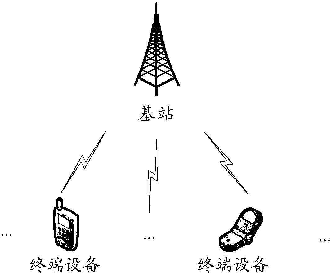
[0061] It should be understood that the network device involved in the embodiments of the present application may be a base station or an access point, or may be a device in an access network that communicates with a wireless terminal through one or more sectors on an air interface. When the network device is a base station, the base station can be used to convert the received air frame and Internet protocol (Internet protocol, IP) packets to each other, as a router between the wireless terminal and the rest of the access network, where the access network The rest can include IP networks. The base station can also be used to coordinate the attribute management of the air interface. For example, the base station can be a base transceiver station (BTS) in a global system for mobile communication (GSM) or a code division multiple access (CDMA)...


PUM


Abstract

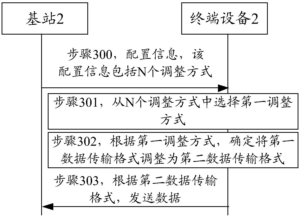
The invention discloses data transmission methods, data transmission devices and a system, and relates to the technical field of communication. One data transmission method comprises the following steps: a network device sends configuration information to a first terminal device, then the first terminal device selects a first adjustment mode from N adjustment modes according to a measurement result after receiving the configuration information sent by the network device, wherein the measurement result is obtained in a manner that the first terminal device measures signals; then, the first terminal device determines to adjust a first data transmission format into a second data transmission format according to the selected first adjustment mode, wherein transmitting power corresponding to the second data transmission format is less than the transmitting power corresponding to the first data transmission format; and finally, the first terminal device sends data to the network device according to the second data transmission format. By the technical scheme above, reduction of cross link interference between the terminal devices is facilitated, and at the same time the utilization rateof time-frequency resource is improved.

Description

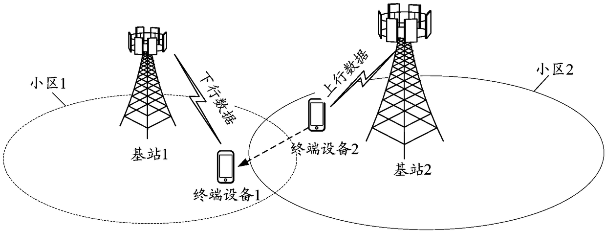
Technical field [0001] This application relates to the field of communication technology, and in particular to a method, device and system for data transmission. Background technique [0002] In a dynamic time division duplexing (D-TDD) system, there may also be cross-link interference between terminal devices. This is because for the same time slot (slot) in a D-TDD system, different base stations The data transmission direction of the terminal device may be different. [0003] Example, such as figure 1 As shown in slot1, base station 1 sends downlink data to terminal device 1 in cell 1, and terminal device 2 in cell 2 sends uplink data to base station 2, where cell 1 is the serving cell of base station 1, and cell 2 is the serving cell of base station 2. . In such figure 1 In the illustrated communication scenario, the uplink data sent by the terminal device 2 will cause interference to the downlink data received by the terminal device 1, and the interference is the cross-link ...

Claims


Application Information

Patent Timeline
IPC IPC(8): H04L1/00H04B15/00H04W24/02H04W72/04
CPCH04B15/00H04L1/0006H04W24/02H04W72/23H04L1/00H04W52/02H04W72/04Y02D30/70
Inventor 马小骏张弛
Owner XFUSION DIGITAL TECH CO LTD
Learn More