Supercharge Your Innovation With Domain-Expert AI Agents!

stator and motor

A technology for stators and motors, which is applied in the directions of electromechanical devices, electrical components, windings, etc., can solve the problems of thickening of the motor thickness and heavy workload, and achieve the effect of miniaturization

Active Publication Date: 2021-07-09
NIDEC CORP
View PDF5 Cites 0 Cited by
  • Summary
  • Abstract
  • Description
  • Claims
  • Application Information

AI Technical Summary

Problems solved by technology

However, in this method, the axial thickness of the motor may become thicker
In addition, when insulating members such as insulating tubes are arranged around the overlapping wires to prevent the overlapping wires from contacting each other, the work load at the time of manufacturing the stator may increase.

Method used


Image

  • stator and motor
  • stator and motor
  • stator and motor

Examples


Embodiment Construction

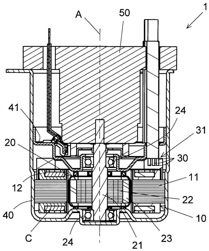
[0023] Hereinafter, exemplary embodiments of the present invention will be described in detail with reference to the drawings. Also, in this manual, the figure 1 The direction in which the central axis A of the motor extends is simply referred to as "axial direction", and the radial and circumferential directions centered on the central axis A of the motor are simply referred to as "radial" and "circumferential". Similarly, for the stator, the directions that coincide with the axial direction, radial direction, and circumferential direction of the motor when assembled in the motor are simply referred to as "axial direction", "radial direction" and "circumferential direction". In this manual, the figure 1 The axial direction in the case where the motor is arranged in the indicated direction is defined as the vertical direction. In addition, "up-and-down direction" is just a name for description, and does not limit the actual positional relationship and direction.

[0024] f...


PUM


Abstract

The annular stator centering on the central axis extending in the up-down direction has: a stator core having a plurality of teeth arranged in the circumferential direction; made. The plurality of coils include coil groups of three phases of U-phase, V-phase, and W-phase, and overlapping lines for relaying the coils of the same phase. On the upper side and the lower side of the stator core, the overlapping wires of one phase are arranged in regions separated from the overlapping wires of the other phase in the circumferential direction.

Description

technical field [0001] The invention relates to stators and motors. Background technique [0002] Japanese Laid-Open Publication No. 2015-211587 discloses a brushless motor including: a cylindrical rotor; and a stator having a space in the center for arranging the rotor. The stator includes: an annular stator core; and first to twelfth teeth, which are sequentially provided along the circumferential direction on the inner peripheral side of the stator core. Conductors are respectively wound around the first to twelfth teeth to form first to twelfth coils. The first to twelfth coils include a U-phase coil, a V-phase coil, and a W-phase coil. [0003] Each phase has a lap wire connecting two coils of the same phase. The lap wires of the respective phases are arranged on the outer edge of one of the axial end faces of the stator core. The bonding wires of the respective phases are arranged so as not to cross each other. When viewed in the axial direction, some overlapping ...

Claims


Application Information

Patent Timeline
Patent Type & Authority Patents(China)
IPC IPC(8): H02K3/50H02K3/28
CPCH02K3/50H02K3/28H02K3/18H02K1/165H02K3/12H02K3/345H02K3/48
Inventor 福永庆介
Owner NIDEC CORP
Features
  • R&D
  • Intellectual Property
  • Life Sciences
  • Materials
  • Tech Scout
  • Unparalleled Data Quality
  • Higher Quality Content
  • 60% Fewer Hallucinations
Learn More