Supercharge Your Innovation With Domain-Expert AI Agents!

Coil component

A technology of coil components and wires, applied in electrical components, transformer/inductor coil/winding/connection, transformer/inductor components, etc. Effect

Active Publication Date: 2020-01-10
MURATA MFG CO LTD
View PDF7 Cites 1 Cited by
  • Summary
  • Abstract
  • Description
  • Claims
  • Application Information

AI Technical Summary

Problems solved by technology

In this way, it can be said that there is almost no degree of freedom in design regarding the shapes of the terminal electrodes 20 to 23 .

Method used


Image

  • Coil component
  • Coil component
  • Coil component

Examples


Embodiment Construction

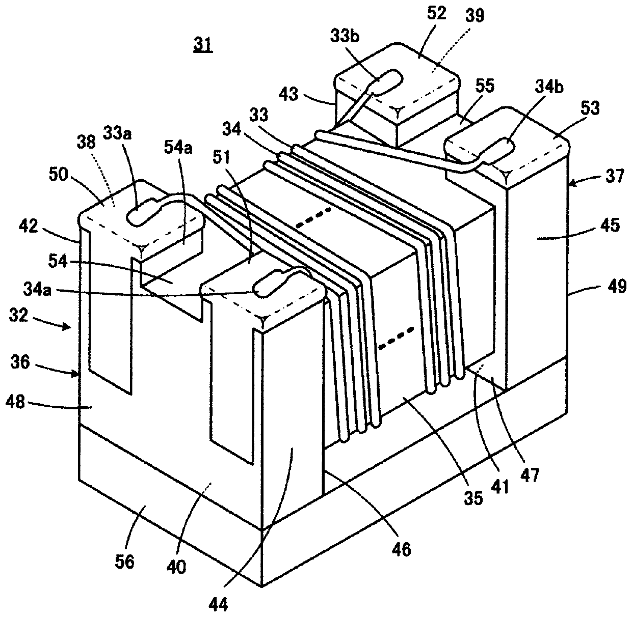
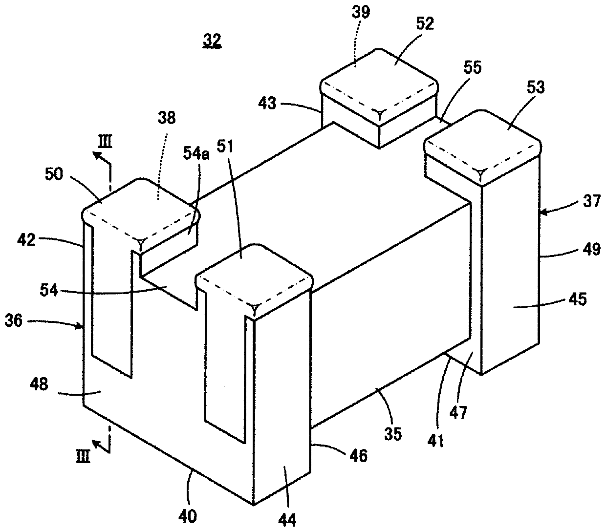
[0030] refer to figure 1 and figure 2 The coil element 31 according to one embodiment of the present disclosure will be described. exist figure 1 and figure 2 In , the coil element 31 and the drum-shaped core 32 are shown so that the surface facing the mounting substrate is upward. The illustrated coil element 31 constitutes, for example, a common mode choke coil.

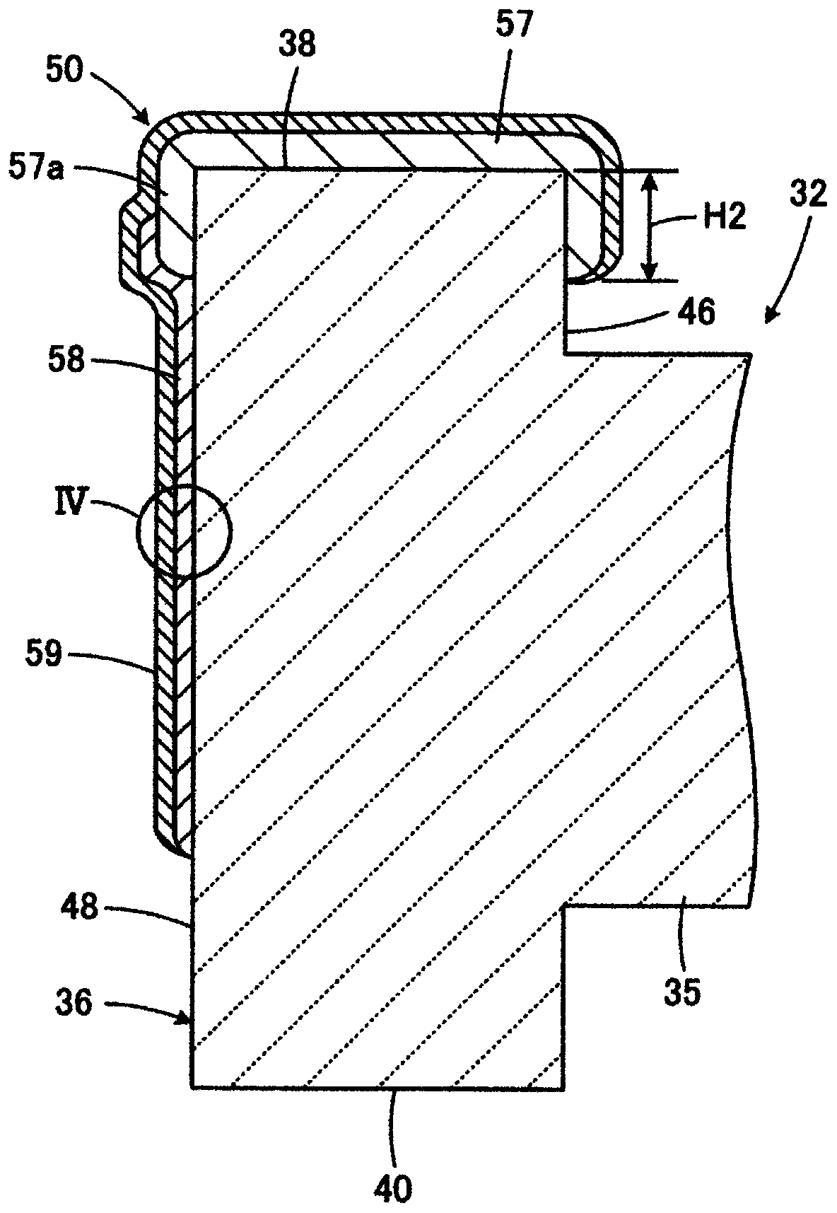
[0031] The drum-shaped core 32 included in the coil element 31 includes: a winding core portion 35 for arranging the first wire 33 and the second wire 34 and extending in the axial direction; The first flange portion 36 and the second flange portion 37 are provided at the second end. The drum core 32 may be made of a non-conductive material, more specifically, a non-magnetic body such as alumina, a magnetic body such as ferrite, or resin, but is preferably made of ceramics such as alumina or ferrite.

[0032]The winding core portion 35 and the first flange portion 36 and the second flange portion 37 inclu...


PUM

PropertyMeasurementUnit
thicknessaaaaaaaaaa
thicknessaaaaaaaaaa

Abstract

The invention provides a coil component (31). A terminal electrode (50) includes a bottom surface electrode portion (57) that is positioned along a bottom surface (38) of a flange part (36), an end surface electrode portion (58) that is positioned along an outer end surface (48) of the flange part (36), and a plating film (59) that covers the bottom surface electrode portion (57) and the end surface electrode portion (58) in a continuous manner. The bottom surface electrode portion (57) contains Ag and Si. The end surface electrode portion (58) is composed of a metal film.

Description

technical field [0001] The present disclosure relates to a coil element, and more particularly, to a winding-type coil element including at least two wires. Background technique [0002] Figure 5 Citing Japanese Patent Application Laid-Open No. 11-204346 (Patent Document 1) figure 1 . Figure 5 The appearance of the drum-shaped core 2 included in the winding-type common mode choke coil as an example of the winding-type coil element is shown. Figure 5 The drum-shaped core 2 is shown in the figure with the surface facing the mounting substrate facing upward. [0003] The common mode choke coil includes a drum-shaped core 2, and first and second wires (not shown) constituting an inductor, respectively. [0004] The drum-shaped core 2 has a winding core portion 5 and a first flange portion 6 and a second flange portion 7 respectively provided at first and second ends of the winding core portion 5 opposite to each other. On the winding core part 5, from the end part on the s...

Claims


Application Information

Patent Timeline
Patent Type & Authority Applications(China)
IPC IPC(8): H01F27/29H01F27/30H01F27/28H01F27/24
CPCH01F27/29H01F27/292H01F27/306H01F27/2823H01F27/24H01F17/045H01F27/2828
Inventor 竹泽香织小林耕平
Owner MURATA MFG CO LTD
Features
  • R&D
  • Intellectual Property
  • Life Sciences
  • Materials
  • Tech Scout
  • Unparalleled Data Quality
  • Higher Quality Content
  • 60% Fewer Hallucinations
Learn More