Supercharge Your Innovation With Domain-Expert AI Agents!

Dish washing machine

A tableware washing machine and tableware technology, which is applied in the direction of tableware washing machine/washing machine, tableware washing machine/rinsing machine parts, cleaning equipment, etc.

Pending Publication Date: 2020-12-15
PANASONIC INTELLECTUAL PROPERTY MANAGEMENT CO LTD
View PDF1 Cites 0 Cited by
  • Summary
  • Abstract
  • Description
  • Claims
  • Application Information

AI Technical Summary

Problems solved by technology

[0003] However, in conventional dishwashers, when the user takes out the filter after washing, the rear bar of the dish basket becomes an obstacle, so it is difficult to put the hand into the filter.
In addition, when taking out the filter, there is a high possibility that the filter will come into contact with the bar behind the cutlery basket, so it is difficult to take out the filter smoothly

Method used


Image

  • Dish washing machine
  • Dish washing machine
  • Dish washing machine

Examples


Embodiment approach 1

[0030] Use the following figure 1 The schematic structure of the dishwasher of Embodiment 1 is demonstrated.

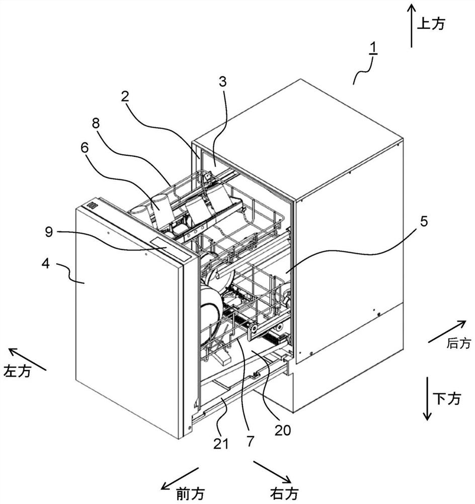
[0031] figure 1 It is a perspective view of the state which pulled the door body 4 forward of the dishwasher 1 which concerns on Embodiment 1 of this invention.

[0032] Such as figure 1 As shown, the dishwasher 1 according to Embodiment 1 includes a washing tank 3 having a front opening 2 , a door 4 , a washing space 5 , a lower dish basket 7 , an upper dish basket 8 , and the like. The door 4 is configured to be able to move back and forth, and to cover the front opening 2 of the washing tub 3 . The cleaning space 5 is formed surrounded by the cleaning tank 3 and the door body 4, and is used for accommodating the lower dish basket 7, the upper dish basket 8, and the like. The lower cutlery basket 7 and the upper cutlery basket 8 are configured to be able to move back and forth, and the objects to be cleaned 6 such as cutlery are placed thereon. The lower cutler...

Embodiment approach 2

[0193] Use below Figure 11A and Figure 11B The dishwasher of Embodiment 2 of this invention is demonstrated.

[0194] In addition, hereinafter, the description will focus on the points of difference from the structure and operation of the dishwasher of Embodiment 1. FIG. Therefore, the same reference numerals are assigned to the same components as those in Embodiment 1, and detailed descriptions of their configurations and operations are omitted.

[0195] Figure 11A It is a perspective view of the lower dish basket 7 of the dishwasher of Embodiment 2. Figure 11B It is a perspective view of the state in which the rear bar part 81 of the lower dish basket 7 of the dishwasher of Embodiment 2 has rotated backward.

[0196] That is, if Figure 11A and Figure 11B As shown, the difference between the lower cutlery basket 7 of the second embodiment and the first embodiment is that the rear bar portion 81 provided at least in part of the rear bar body 79 is configured to be ...

Embodiment approach 3

[0200] Use below Figure 12A and Figure 12B A dishwasher according to Embodiment 3 of the present invention will be described.

[0201] In addition, below, it demonstrates centering on the difference in structure and operation|movement from the dishwasher of Embodiment 1, 2. Therefore, the same reference numerals are assigned to the same components as those in Embodiments 1 and 2, and detailed descriptions of their configurations and operations are omitted.

[0202] Figure 12A It is a perspective view of the lower dish basket 7 of the dishwasher of Embodiment 3. Figure 12B It is a perspective view of the state which the rear bar part 81 of the lower dish basket 7 of the dishwasher of Embodiment 3 slid downward.

[0203] That is, if Figure 12A and Figure 12B As shown, the difference between the lower cutlery basket 7 of Embodiment 3 and the above-mentioned Embodiments 1 and 2 is that the rear bar portion 81 provided at least in part of the rear bar body 79 is configu...


PUM

PropertyMeasurementUnit
Diameteraaaaaaaaaa

Abstract

A rear strip (79) of a lower dish basket (7) of a dish washing machine (1) has a movable rear strip part (81) at least in some regions. The rear strip part (81) is located in front of the drain filter(50) when the lower basket (7) is pulled out, and constitutes a rear space part (80) by movement. Thereby, after cleaning, a user can place a hand into the drainage filter (50) through the rear spacepart (80), take out the drainage filter (50), and remove the collected residue. In addition, when the drainage filter (50) is taken out, the drainage filter (50) is not prone to making contact with the rear strip body part (81) after movement. Therefore, the drainage filter (50) can be easily removed from the dishwasher (1). As a result, it is possible to provide a dishwasher (1) having excellentmaintainability.

Description

technical field [0001] The present invention relates to a dishwasher with a structure in which a dish basket on which objects to be washed such as tableware are placed is pulled out from a washing tank forward. Background technique [0002] For example, as disclosed in Japanese Patent Application Laid-Open No. 2008-119205 (hereinafter referred to as Patent Document 1), conventional dishwashers include a dish basket and a filter. The washing tank is constituted by a bar pulled out to the front, and the filter is provided behind the cutlery basket to collect residues of food and the like that flow down during washing. [0003] However, in the conventional dishwasher, when the user takes out the filter after washing, the rear bar of the dish basket becomes an obstacle, so it is difficult to put the hand into the filter. In addition, when the filter is taken out, there is a high possibility that the filter will come into contact with the rear bar of the cutlery basket, so it is...

Claims


Application Information

Patent Timeline
IPC IPC(8): A47L15/23A47L15/42A47L15/50
CPCA47L15/23A47L15/42A47L15/4202A47L15/4223A47L15/501A47L15/502A47L15/507A47L15/4246A47L2601/03
Inventor 澁谷昌树菊川智之西村诚
Owner PANASONIC INTELLECTUAL PROPERTY MANAGEMENT CO LTD
Features
  • R&D
  • Intellectual Property
  • Life Sciences
  • Materials
  • Tech Scout
  • Unparalleled Data Quality
  • Higher Quality Content
  • 60% Fewer Hallucinations
Learn More