Supercharge Your Innovation With Domain-Expert AI Agents!

Packaging structure and packaging process for battery electrode plate

A technology of battery pole piece and packaging process, applied in non-aqueous electrolyte battery electrodes, secondary batteries, structural parts, etc., can solve the problems of active material layer peeling, mutual contact, battery damage, etc., to achieve good stability, not easy to contact , to avoid the effect of short circuit

Inactive Publication Date: 2016-08-10
GUANGDONG ZHICHENG CHAMPION GROUP
View PDF4 Cites 0 Cited by
  • Summary
  • Abstract
  • Description
  • Claims
  • Application Information

AI Technical Summary

Problems solved by technology

Most of the existing lithium-ion batteries are made by stacking positive and negative pole pieces, and there is an insulating diaphragm or insulating coating layer between the positive pole piece and the negative pole piece, and the active material layer is welded on the pole piece, and the tab is welded. The existing insulating diaphragm is wound or stacked on the surface of the positive pole piece or the negative pole piece to insulate the positive and negative pole pieces. At least one side of the insulating membrane has an opening structure that can expose the pole piece. Due to the opening structure and the pole piece is not completely sealed, the active material layer on the pole piece has a great chance to fall off, and the active material material after falling off will leak from the opening, and the leakage of the active material will have a negative impact on battery performance. Self-discharge may even occur, causing irreversible damage to the battery
At the same time, due to the above-mentioned opening structure, there may be mutual contact between the pole pieces, which is likely to cause a short circuit, thereby causing more serious accidents, which limits the improvement of battery power to a certain extent.

Method used


Image

  • Packaging structure and packaging process for battery electrode plate
  • Packaging structure and packaging process for battery electrode plate
  • Packaging structure and packaging process for battery electrode plate

Examples


Embodiment 1

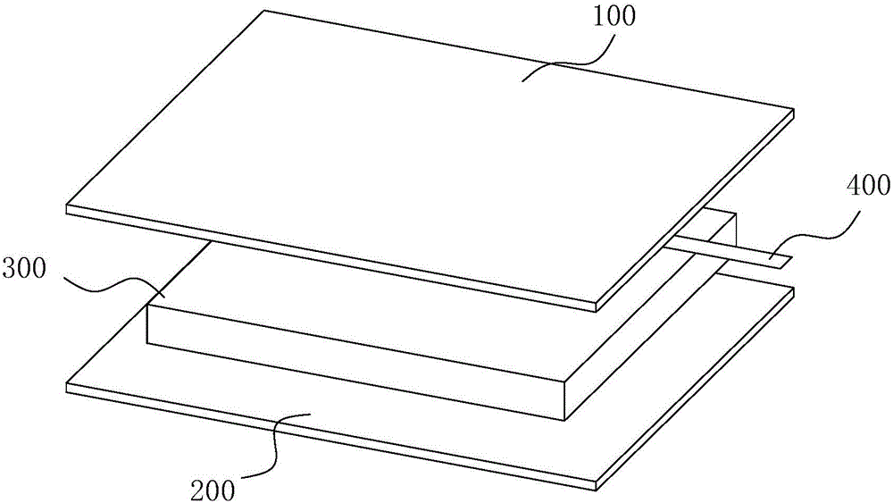
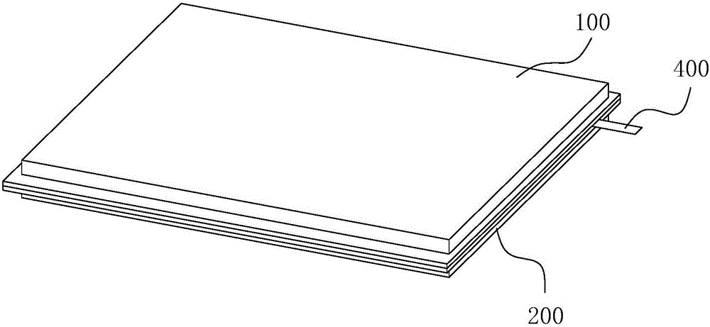
[0032] figure 1 It is a schematic diagram of the disassembled state of the battery pole piece packaging structure described in Embodiment 1 of the present invention; figure 2 It is a structural schematic diagram of the battery pole piece packaging structure described in Embodiment 1 of the present invention after pressing and bonding; figure 1 , 2 As shown, a battery pole sheet packaging structure includes an electrode sheet 300 and a diaphragm, the electrode sheet 300 has a first surface and a second surface opposite to each other, and the diaphragm includes electrodes corresponding to the first surface and the second The first diaphragm 100 and the second diaphragm 200 arranged on the surface, the first diaphragm 100 and the second diaphragm 200 are connected to each other at the periphery of the electrode sheet 300, and the diaphragm is provided with a pole piece for connecting the pole piece. The tab mounting hole of the ear 400.

[0033] In this embodiment, the first ...

Embodiment 2

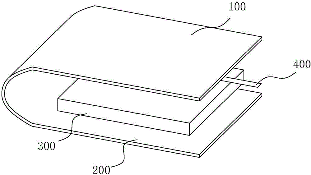
[0044] image 3 It is a schematic diagram of the disassembled state of the battery pole piece packaging structure described in Embodiment 2 of the present invention; image 3 As shown, a battery pole sheet packaging structure includes an electrode sheet 300 and a diaphragm, the electrode sheet 300 has a first surface and a second surface opposite to each other, and the diaphragm includes electrodes corresponding to the first surface and the second The first diaphragm 100 and the second diaphragm 200 arranged on the surface, the first diaphragm 100 and the second diaphragm 200 are connected to each other at the periphery of the electrode sheet 300, and the diaphragm is provided with a pole piece for connecting the pole piece. The tab mounting hole of the ear 400.

[0045] In this embodiment, the sheet structure of the first diaphragm 100 and the second diaphragm 200 is respectively located on the first surface and the second surface of the electrode sheet 300 after being bent,...

Embodiment 3

[0054] Figure 4 It is a schematic diagram of the decomposed state of the battery pole piece packaging structure described in Embodiment 3 of the present invention; Figure 4 As shown, in this embodiment, a bag-shaped separator with only one side opening is used as the first separator 100 and the second separator 200, and after the electrode sheet 300 is loaded into the bag-shaped separator from the opening, the opening is pressed and bonded, and the pressure During the bonding process, a tab installation hole is reserved for the protrusion of the tab 400. In this embodiment, the pressing bonding can be cold pressing bonding or hot pressing bonding.

[0055] The battery pole piece with this encapsulation structure can avoid the leakage of the active material in the battery, the contact between the pole pieces is not easy to occur, and the hidden danger of short circuit is avoided; the battery produced by this process has good stability and can be applied to large The producti...


PUM


Abstract

The invention discloses a packaging structure for a battery electrode plate. The packaging structure comprises an electrode plate and diaphragms, wherein the electrode plate has a first surface and a second surface which are arranged in opposite; the diaphragms comprise a first diaphragm and a second diaphragm which are arranged corresponding to the first surface and the second surface respectively; the first diaphragm and the second diaphragm are connected on the circumference of the electrode plate; and a tab mounting hole for enabling the electrode plate to be connected with a tab is formed in the diaphragms; and meanwhile, the invention also discloses a packaging process for the battery electrode plate, and an electrode plate group and a battery adopting the battery electrode plate. According to the battery electrode plate with the packaging structure, the leakage of the active material in the battery can be avoided; the electrode plates are not contacted easily, so that the hidden danger of short circuits is avoided; the battery produced by the process is high in stability, so that the process can be applied to production of high-power batteries; the electrode plate group is subjected to secondary packaging through a packaging bag, so that the leakage of the active material is further avoided; and in addition, the battery adopting the structure or the process is stable in electric quantity and safe to use.

Description

technical field [0001] The invention relates to the technical field of battery production, in particular to a battery pole piece packaging structure and a packaging process thereof. Background technique [0002] Today, portable electronic products have become an indispensable tool, and people urgently need batteries with high power, high stability, and high safety to meet the increasing demand for battery performance in electronic products. Most of the existing lithium-ion batteries are made by stacking positive and negative pole pieces, and there is an insulating diaphragm or insulating coating layer between the positive pole piece and the negative pole piece, and the active material layer is welded on the pole piece, and the tab is welded. The existing insulating diaphragm is wound or stacked on the surface of the positive pole piece or the negative pole piece to insulate the positive and negative pole pieces. At least one side of the insulating membrane has an opening str...

Claims


Application Information

Patent Timeline
Patent Type & Authority Applications(China)
IPC IPC(8): H01M2/14H01M4/13H01M10/04H01M10/0525H01M50/403
CPCH01M4/13H01M10/0459H01M50/40Y02E60/10Y02P70/50
Inventor 郭泉锋蒋连喜
Owner GUANGDONG ZHICHENG CHAMPION GROUP
Features
  • R&D
  • Intellectual Property
  • Life Sciences
  • Materials
  • Tech Scout
  • Unparalleled Data Quality
  • Higher Quality Content
  • 60% Fewer Hallucinations
Learn More