Dust separator and vacuum cleaner

A technology of dust separation and cyclone separation device, which is applied in the field of sanitary tools, can solve the problems such as the inability of the motor to dissipate heat, the reduced dust suction ability, and the inconvenience of the user, so as to achieve the effect of improving the dust suction effect, reducing the cleaning frequency and improving the service life.

Pending Publication Date: 2019-03-19
深圳市蓝达镭得科技有限公司
View PDF0 Cites 8 Cited by
  • Summary
  • Abstract
  • Description
  • Claims
  • Application Information

AI Technical Summary

Problems solved by technology

But for hair, ribbons, flour and other dust, the separation effect is relatively poor, especially when the ribbon is wrapped around the cyclone cone, the ability to separate dust as fine as flour will be lost, and it can only be intercepted and filtered by filter cloth or Hypa , it is easy to cause blockage of the filter cloth or Hypa, resulting in the rapid loss of the product's dust-absorbing ability. At this time, it is necessary to clean the cyclone cone and clean the filter cloth or Hypa immediately, otherwise the motor will not be able to dissipate heat and burn down
[0003] In addition, the dust separation device of some existing horizontal vacuum cleaners and portable dual-purpose stick vacuum cleaners directly uses filter cloth or Hypa to directly intercept and filter the dust. It is easier to drop sharply, causing the product to be unable to vacuum or seriously causing the motor to be unable to dissipate heat and burn out
[0004] Moreover, the vacuum cleaner using the above-mentioned dust separation device in the related art needs to frequently clean the cyclone cone or clean the filter cloth or hypa, which causes inconvenience to the user, and at the same time, it is easy to cause the motor to be unable to dissipate heat and burn out.

Method used


Image

  • Dust separator and vacuum cleaner
  • Dust separator and vacuum cleaner
  • Dust separator and vacuum cleaner

Examples


Embodiment Construction

[0023] The present invention will be further described below in conjunction with the accompanying drawings and embodiments.

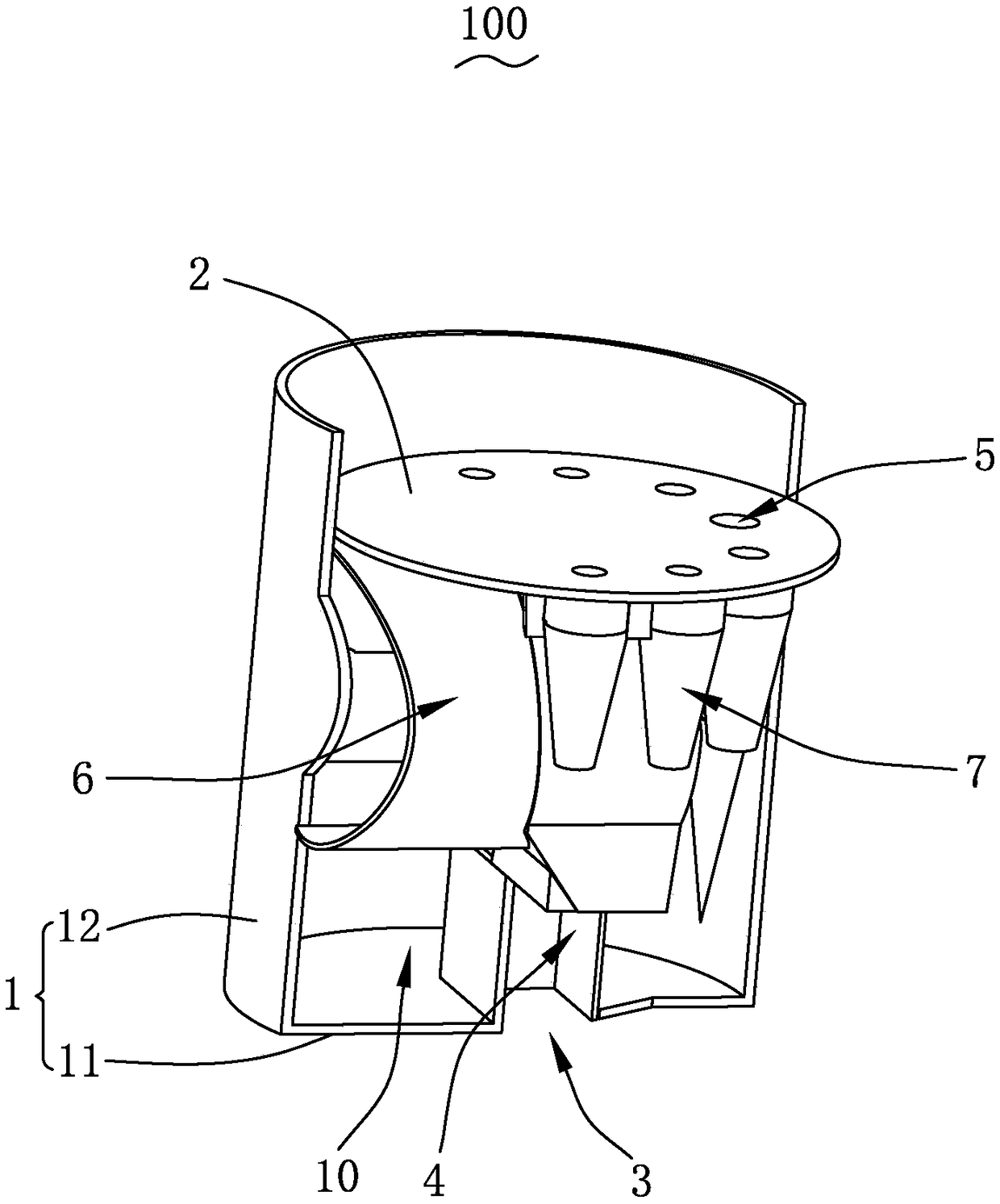
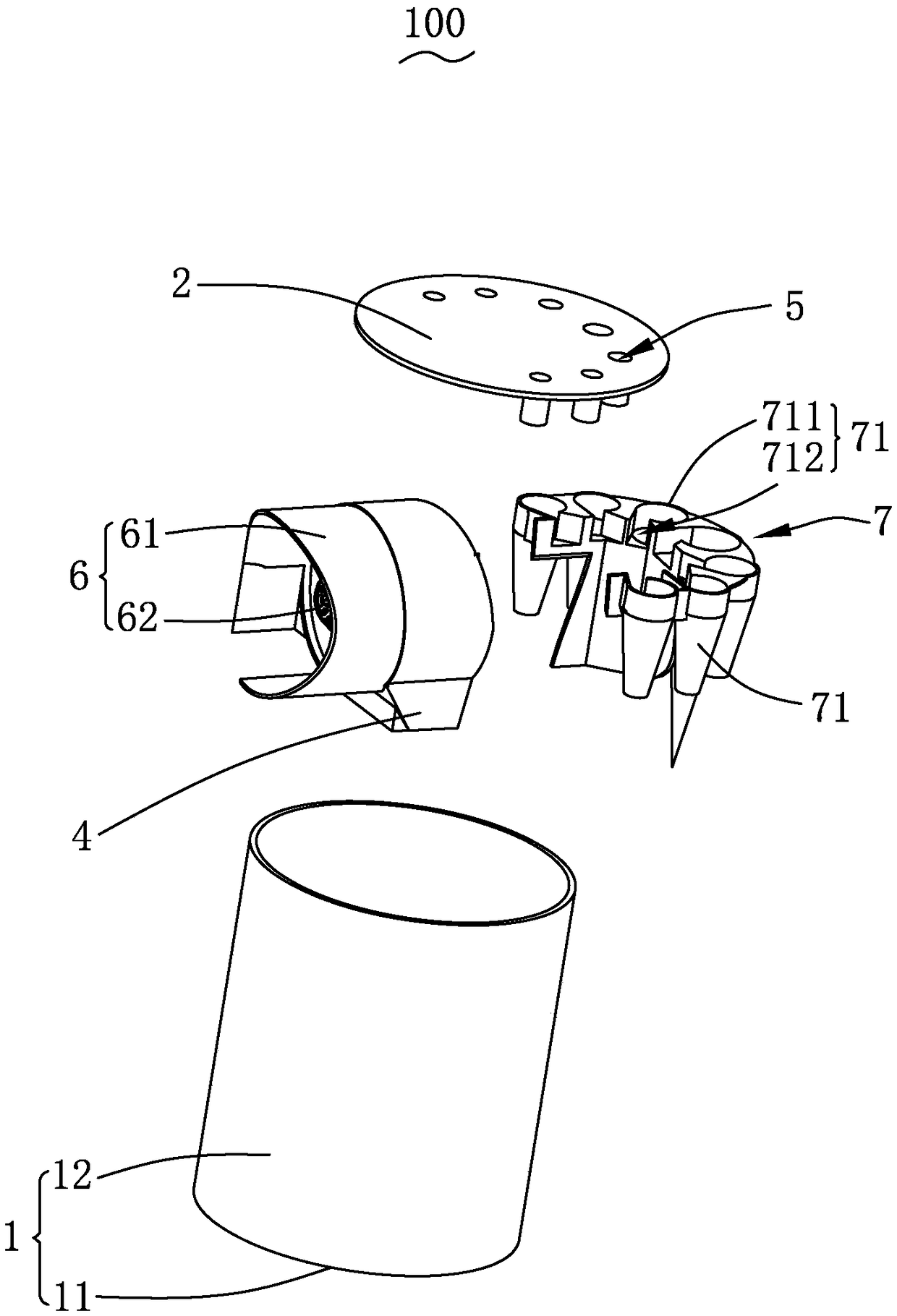
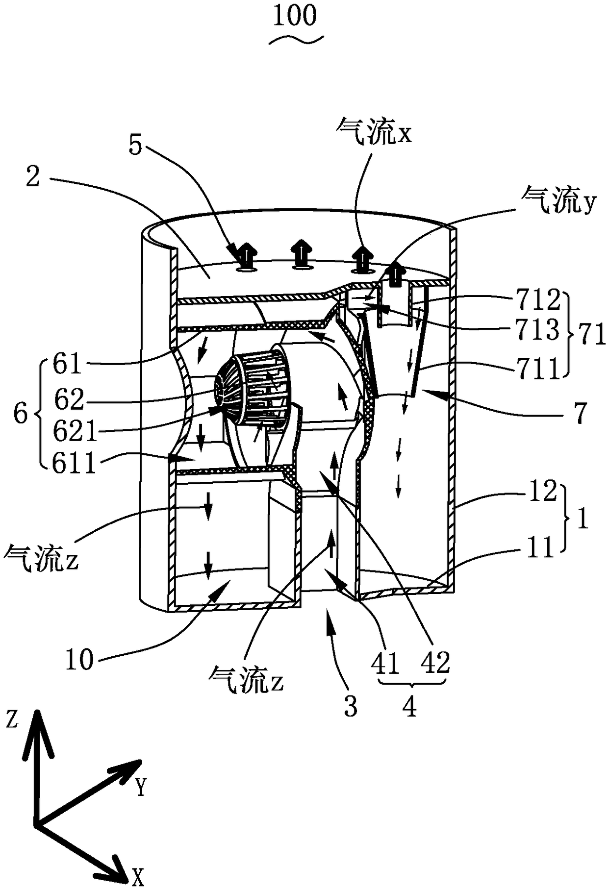
[0024] Please also refer to Figure 1-3 As shown, the present invention provides a dust separation device 100, including a dust bucket 1, a cover plate 2, a dust inlet 3, a dust inlet channel 4, an exhaust hole 5, a first-stage separation unit 6 and a second-stage separation unit 7 , the cover plate 2 is arranged on the dust bucket 1 and jointly forms a receiving space 10 .

[0025] The dust bucket 1 includes a bottom wall 11 and a side wall 12 bent and extended from the periphery of the bottom wall 11 , and the cover plate 2 is provided on an end of the side wall 12 away from the bottom wall 11 . The dust bucket is cylindrical, conical or square.

[0026] The dust inlet 3 is provided through the dust bucket 1 . In this embodiment, the position of the dust inlet 3 can be set at any position of the dust bucket 1, for example, the dust inlet 3 is set t...


PUM


Abstract

The invention provides a dust separator, comprising a dust barrel, a cover plate that covers the dust barrel to jointly form a receiving space, a dust inlet running through the dust barrel, a dust incoming passage formed in the receiving space and communicated with the dust inlet, an exhaust hole running through the cover plate, and primary and secondary separation units mounted in the receiving space. The primary separation unit has horizontally arranged axis, and the secondary separation unit has vertically arranged axis; the secondary separation unit is arranged downstream of the primary separation unit along the flow direction and is serially connected with the primary separation unit. The invention also provides a vacuum cleaner. Compared with the prior art, the dust separator and thevacuum cleaner have high dust suction capacity, long service lives and low cleaning frequency.

Description

technical field [0001] The invention relates to the field of sanitary tools, in particular to a dust separating device and a vacuum cleaner. Background technique [0002] The existing horizontal vacuum cleaners and portable dual-purpose stick vacuum cleaners on the market are basically in the form of one-stage separation as long as the dust separation device using the cyclone cone to separate dust is used. , paper shreds, beans, etc.) have a good separation effect. But for hair, ribbons, flour and other dust, the separation effect is relatively poor, especially when the ribbon is wrapped around the cyclone cone, the ability to separate dust as fine as flour will be lost, and it can only be intercepted and filtered by filter cloth or Hypa , This will easily cause the filter cloth or Hypa to be clogged, resulting in the rapid loss of the product's dust-absorbing ability. At this time, it is necessary to clean the cyclone cone and clean the filter cloth or Hypa immediately, ot...

Claims


Application Information

Patent Timeline
Patent Type & Authority Applications(China)
IPC IPC(8): A47L9/16A47L9/00
CPCA47L9/102A47L9/00A47L9/16A47L9/1683
Inventor 邓培海
Owner 深圳市蓝达镭得科技有限公司
Why Eureka
Try Eureka