
Concrete vibrator for easy support and working method thereof

A vibrator and concrete technology, which is applied in the processing of building materials, construction, building construction, etc., can solve the inconvenience of adjusting the height of the scraping teeth, the inclination angle of the vibrating rod, and the auxiliary scraping of concrete with different heights equality issue

Inactive Publication Date: 2020-11-13
河南七建工程集团有限公司
View PDF1 Cites 0 Cited by
  • Summary
  • Abstract
  • Description
  • Claims
  • Application Information

AI Technical Summary

Problems solved by technology

[0006] In order to solve the above technical problems, the present invention provides a conveniently supported concrete vibrator and its working method to solve the problem that the existing supported concrete vibrator does not have the ability to adjust the inclination of the lower end of the vibrator according to the needs of use. The angle does not have the effect of auxiliary scraping on concrete with different heights, it is inconvenient to adjust the height of the scraping teeth, it does not have the problem of buffering the vibrating rod and poor protection effect when the vibrating rod is fixed

Method used


Image

  • Concrete vibrator for easy support and working method thereof
  • Concrete vibrator for easy support and working method thereof
  • Concrete vibrator for easy support and working method thereof

Examples


Embodiment

[0043] as attached figure 1 And attached figure 2 shown

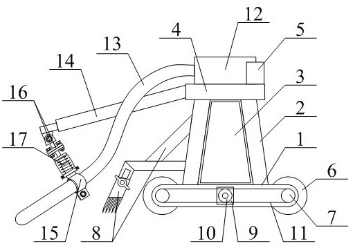
[0044] The present invention provides a concrete vibrator that is easy to support, including a transverse bottom plate 1, support legs 2, a tool storage frame 3, a transverse plate 4, a junction box 5, a moving wheel 6, a driven wheel 7, and an adjustable auxiliary scraping frame structure 8. Drive motor 9, driving wheel 10, transmission belt 11, vibrating motor 12, vibrating rod 13, mounting frame 14, clamping fixed frame structure 15, angle adjustment fixed frame structure 16 and buffer bracket structure 17, the support The bolts of leg 2 are installed on the left and right sides of the upper part of the transverse bottom plate 1; the screws of the tool storage frame 3 are installed on the inner side of the supporting leg 2; the bolts of the transverse plate 4 are installed on the upper part of the supporting leg 2; the junction box 5 screws are installed on the upper right side of the transverse plate 4; the movin...


PUM


Abstract

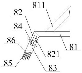
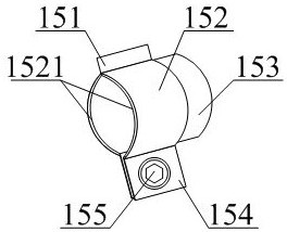
The invention provides a concrete vibrator convenient to support and a working method thereof. The concrete vibrator comprises a transverse bottom plate, supporting legs, a tool storage frame, a transverse plate, a junction box, a moving wheel, a driven wheel, an adjustable auxiliary scraping frame structure, a driving motor, a driving wheel, a transmission belt, a vibrating motor, a vibrating rod, a mounting frame, a clamping and fixing frame structure, an angle adjusting fixing frame structure and a buffering support structure. An adjustable bolt nut is in threaded connection with the jointof a top shaft frame and a bottom shaft frame, and the angle between the top shaft frame and the bottom shaft frame can be adjusted conveniently, so that the inclination angle of the vibrating rod isconveniently adjusted. Stainless steel scraping teeth are sequentially welded to the lower portion of the transverse mounting plate from front to back so that concrete with different heights can be subjected to scraping assisting during use; a jacking bolt is in threaded connection with the joint between a scraping rod and the front side of a scraping pipe so that the length of the portion, sleeving a hanging rod, of the scraping pipe can be adjusted, and then the height of the stainless steel scraping teeth can be conveniently adjusted.

Description

technical field [0001] The invention belongs to the technical field of building construction tools, and in particular relates to a concrete vibrator which is easy to support and a working method thereof. Background technique [0002] During the building construction process, the cast-in-place concrete needs to be vibrated to make the internal texture of the concrete uniform and eliminate internal air bubbles. The current concrete vibrator mainly includes a vibrating rod with an eccentric mechanism inside, and the eccentric mechanism is driven by a driving flexible shaft outside the vibrating rod to generate mechanical waves of transverse vibration. A common eccentric mechanism includes a rotating shaft driven by a drive flexible shaft, one side of the rotating shaft is fixed with a counterweight along the generatrix, and a transverse mechanical wave is generated through the rotation of the counterweight; however, the form of the mechanical wave generated by this vibrator is ...

Claims


Application Information

Patent Timeline
Patent Type & Authority Patents(China)
IPC IPC(8): E04G21/08
CPCE04G21/08
Inventor 许艳阳李忠治罗秋贵史兴朋郭书启崔洪山
Owner 河南七建工程集团有限公司
Learn More