Lightweight concrete internal and external corner structure in fabricated building and mounting method
A light-weight concrete and prefabricated technology, which is applied in the direction of building structure, construction, covering/lining, etc., can solve the problems of inability to install right-angled walls and inconvenient structural adjustment of yin and yang corners, so as to reduce limitations and facilitate Effect of dismantling and improving stability
- Summary
- Abstract
- Description
- Claims
- Application Information
AI Technical Summary
Problems solved by technology
Method used
Image
Examples
Embodiment 1
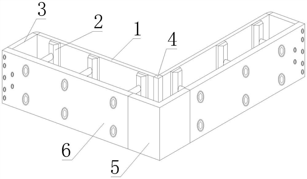
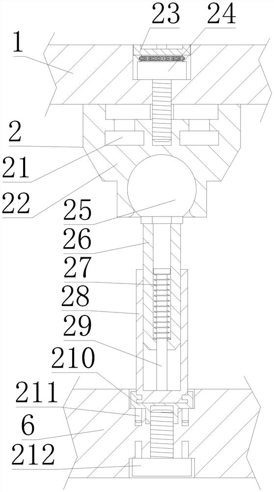
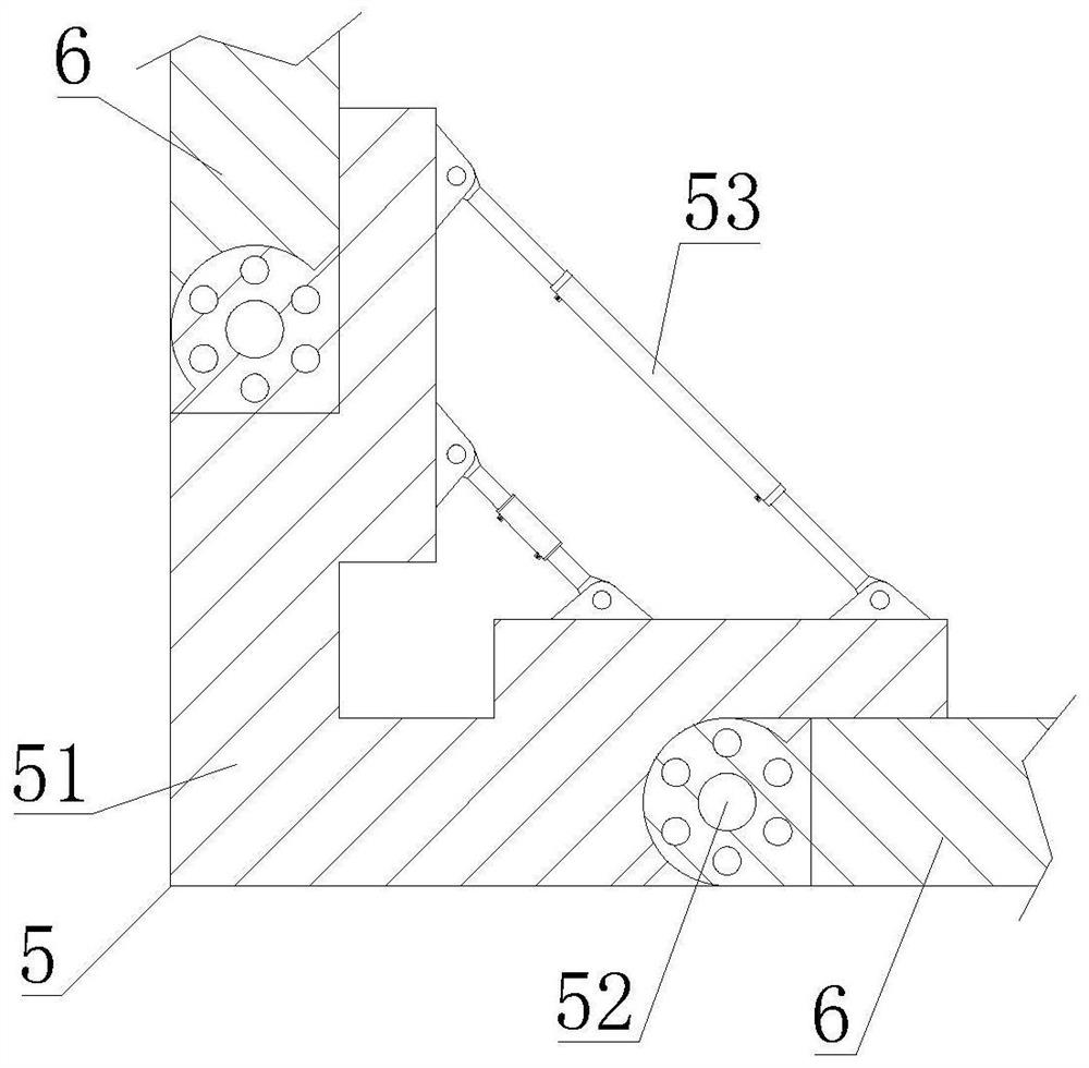
[0053] First aspect, such as Figure 1-5 As shown, the present invention provides a light-weight concrete yin and yang corner structure in a prefabricated building, including an external panel 6, a second right angle 5 is arranged between the external panel 6 and the external panel 6, and the right end of the external panel 6 A support plate 3 is fixedly installed, one end of the support plate 3 is rotatably connected to a built-in plate 1, a first right angle 4 is clamped between the built-in plate 1 and the built-in plate 1, and an angle is fixedly installed between the built-in plate 1 and the external plate 6 The adjustment structure 2, the angle adjustment structure 2 includes a first fixing stud 24 and a second fixing stud 212, the outer wall of the first fixing stud 24 is inserted into the front of the built-in board 1, and the bottom thread of the outer wall of the first fixing stud 24 Connected with an external cardboard spherical seat 22, the front of the built-in bo...
Embodiment 2
[0056] Such as Figure 1-5 As shown, on the basis of Embodiment 1, the present invention provides a technical solution: preferably, the top of the inner wall of the outer clamping plate spherical seat 22 is slidably connected with the built-in clamping block 21, and the top of the built-in clamping block 21 is connected to the built-in plate 1 The bottom of the outer clamping plate spherical seat 22 is fixedly installed, the inner wall of the external clamping plate spherical seat 22 is provided with a ball head 25, the bottom of the ball head 25 is fixedly installed with a threaded adjustment rod 26, and the top of the second fixed stud 212 outer wall is threaded with a fixed card seat 210, The bottom of fixed deck 210 is fixedly connected with positioning pin 211, and the inner wall of fixed deck 210 is connected with threaded bushing 28, and the inner wall of threaded bushing 28 is threadedly connected with the bottom of threaded adjusting rod 26 outer walls, and the inner w...
Embodiment 3
[0059] Such as Figure 1-5 As shown, on the basis of Embodiment 1, the present invention provides a technical solution: preferably, the connection structure 52 includes a threaded tie rod 522, the outer wall of the threaded tie rod 522 is plugged with one end of the outer plate 6, and the outer wall of the threaded tie rod 522 The bottom is plugged with a lower fixed disk 524, the top of the threaded pull rod 522 outer wall is provided with an upper fixed disk 521, the bottom of the upper fixed disk 521 is fixedly connected with a positioning guide 526, and the top of the positioning guide 526 inner wall is fixedly equipped with a high elastic spring 523. A positioning guide post 525 is fixedly installed on the top of the fixed plate 524 , and the bottom of the high elastic spring 523 overlaps with the top of the positioning guide post 525 .
[0060] In this embodiment, when the yin and yang angle structure is in the yang angle structure, the function of the threaded rod 522 a...
PUM
 Abstract
Description
Claims
Application Information
 - R&D
- Intellectual Property
- Life Sciences
- Materials
- Tech Scout
- Unparalleled Data Quality
- Higher Quality Content
- 60% Fewer Hallucinations
Browse by: Latest US Patents, China's latest patents, Technical Efficacy Thesaurus, Application Domain, Technology Topic, Popular Technical Reports.
© 2025 PatSnap. All rights reserved.Legal|Privacy policy|Modern Slavery Act Transparency Statement|Sitemap|About US| Contact US: help@patsnap.com


