Shaft displacement prevention device for mechanical transmission type grate cooler

A transmission-type, cold machine technology, applied in the direction of mechanical equipment, engine components, engine lubrication, etc., can solve problems such as loose bearing components, impact vibration of the main drive shaft, and unstable transmission, so as to reduce the number of pauses and ensure stability running effect

Active Publication Date: 2019-03-19
NANJING RUITAI CEMENT MFG EQUIP CO LTD
View PDF3 Cites 0 Cited by
  • Summary
  • Abstract
  • Description
  • Claims
  • Application Information

AI Technical Summary

Problems solved by technology

In the actual production process, due to the disadvantage of unstable transmission in the chain transmission structure, the main transmission shaft will be subject to frequent impact and vibration, which will easily cause the bearing components to loosen and the bearing to run away from the inner sleeve, which often leads to the main transmission shaft of the grate cooler. Shaft phenomenon, the main drive shaft is displaced in the axial direction; this is a common problem of this type of equipment
Once the main transmission shaft of the grate cooler moves, it is necessary to stop the material and stop the kiln for emergency repair, which seriously affects the stable operation of the firing system. At the same time, the existing device does not have a device to prevent the shaft from jumping during operation. Lubricating oil function during the process

Method used


Image

  • Shaft displacement prevention device for mechanical transmission type grate cooler
  • Shaft displacement prevention device for mechanical transmission type grate cooler
  • Shaft displacement prevention device for mechanical transmission type grate cooler

Examples


Embodiment Construction

[0023] The following will clearly and completely describe the technical solutions in the embodiments of the present invention with reference to the accompanying drawings in the embodiments of the present invention. Obviously, the described embodiments are only some, not all, embodiments of the present invention. Based on the embodiments of the present invention, all other embodiments obtained by persons of ordinary skill in the art without making creative efforts belong to the protection scope of the present invention.

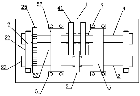
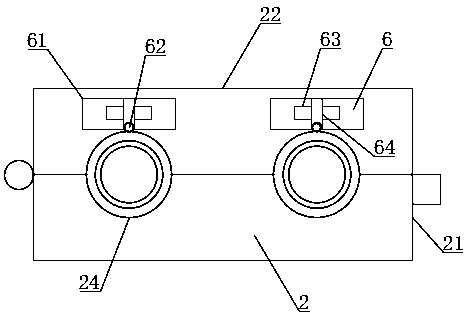
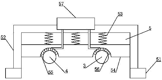
[0024] see Figure 1-5 , the present invention provides a technical solution: a mechanically driven type refrigerator shaft release device, including a base 1, the two ends of the base 1 are provided with a mounting mechanism 2, and the two mounting mechanisms 2 are respectively A rotating shaft 3 and an auxiliary shaft 4 are movably installed through bearings. A fixed plate 41 is fixedly arranged on the outer sides of both ends of the middle part of the auxil...


PUM


Abstract

The invention discloses a shaft displacement prevention device for a mechanical transmission type grate cooler. The device comprises a base, mounting mechanisms are arranged at the two ends of the base, a rotating shaft and an auxiliary shaft are movably arranged between the two mounting mechanisms through bearings correspondingly, fixing discs are fixedly arranged on the outer sides of the two ends of the middle of the auxiliary shaft, a baffle is fixedly arranged on the outer side of the middle of the rotating shaft, the baffle is arranged between the two fixing discs, and fixing mechanismsare arranged at the two ends of the rotating shaft and the auxiliary shaft. According to the device, the auxiliary shaft is driven to rotate through a gear while the rotating shaft rotates, meanwhile,a ball is driven to rotate while rotating, then lubricating oil on the inner side of an oil box is brought to the bearing where the rotating shaft is located and the bearing where the auxiliary shaftis located through the ball for lubricating and cooling, so that the situation that the bearings are damaged and broken due to the facts that rotating is performed for a long time and the lubricatingoil is not provided for lubricating and cooling and other problems occur, so that the production efficiency is reduced is avoided.

Description

technical field [0001] The invention relates to the field of a shaft releasing device for a mechanical transmission type refrigerator, in particular to a shaft releasing device for a mechanical transmission type refrigerator. Background technique [0002] In the cement production industry, grate coolers (which can be referred to as grate coolers for short) are needed in the clinker production line; the current grate coolers mainly include two types: mechanical transmission type and hydraulic transmission type; among them, the mechanical transmission type grate cooler , each section of the grate bed has a set of independent mechanical propulsion devices, and the transmission device is a chain transmission structure. In the actual production process, due to the disadvantage of unstable transmission in the chain transmission structure, the main transmission shaft will be subjected to frequent impact and vibration, which will easily cause the bearing components to loosen and the...

Claims


Application Information

Patent Timeline
Patent Type & Authority Applications(China)
IPC IPC(8): F27D15/02C04B7/47F16N11/08
Inventor 羊华
Owner NANJING RUITAI CEMENT MFG EQUIP CO LTD
Why Eureka
Try Eureka