a clutch switch

A technology of clutch switch and ejector rod, applied in the direction of contact operating parts, etc., can solve the problems of easy fatigue deformation of the moving contact piece, poor contact between the moving contact piece and the fixed terminal, etc., so as to improve the use experience, increase the service life, reduce the The effect of rigid touch

Active Publication Date: 2020-04-17
ZHEJIANG YANGMING AUTO PARTS
View PDF5 Cites 0 Cited by
  • Summary
  • Abstract
  • Description
  • Claims
  • Application Information

AI Technical Summary

Problems solved by technology

[0005] The present invention aims to overcome the deficiency that the movable contact piece of the clutch switch in the prior art is easily fatigued and deformed, resulting in poor contact between the movable contact piece and the fixed terminal. The bonding pressure of the static contact piece reduces the deformation of the moving contact piece and improves the service life of the moving contact piece

Method used


Image

  • a clutch switch

Examples


Embodiment Construction

[0020] The present invention will be further described below in conjunction with the accompanying drawings and specific embodiments.

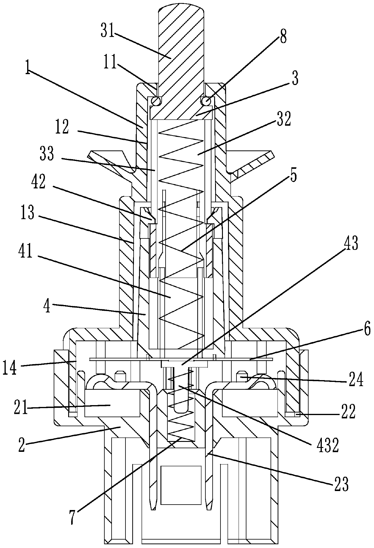
[0021] figure 1 Among them, a clutch switch includes a housing 1 and a base 2 located below the housing. The housing 1 is in the shape of a stepped shaft. The housing 1 is provided with a stepped through hole composed of three sections of circular holes. The diameters of the stepped through holes from top to bottom are in order The stepped through hole is divided into a second round hole 12 , a third round hole 13 and a fourth round hole 14 from top to bottom. An annular groove 22 is provided on the upper side of the base 2 , and the lower end of the housing 1 is inserted into the annular groove 22 to be fixed. The base 2 is fixed with a pin 23, the pin 23 is provided with a static contact piece 24, the housing 1 is provided with a push rod 3, and the push rod 3 is slidably connected to a push rod seat 4, between the ejector rod 3 and the ejec...


PUM


Abstract

The invention discloses a clutch switch comprising a casing and a base arranged under the casing. Plugging pins are fixed on the base; and static contact pieces are arranged at the plugging pin. A mandril is arranged in the casing and is connected with a mandril base in a sliding manner; a first spring is disposed between the mandril and the mandril base. Moving contact pieces opposite to the static contact pieces are arranged at the lower end of the mandril base; and a second spring is disposed between the mandril base and the base. The clutch switch has the following advantages: the servicelife of the mandril is prolonged; the service life of the moving contact piece is prolonged; the rigid contact between the moving contact piece and the static contact piece is reduced and the servicelife of the moving contact piece is prolonged; the sound of the collision between the moving contact piece and the static contact piece is reduced; the use experience of the clutch switch is improved;the elastic force on the outer casing during returning of the push rod is reduced; and thus the overall service life of the clutch switch is prolonged.

Description

technical field [0001] The invention relates to the technical field of automobile braking, in particular to a clutch switch. Background technique [0002] The clutch switch is mainly used to provide a signal for turning on the engine and switching the power of the gearbox. The clutch switch is a normally closed switch. The clutch switch is usually installed on the clutch pedal of the car. When the clutch pedal is not pressed, the ejector rod is in the In the compression state, the clutch switch is in the on state; when the clutch pedal is stepped on, the ejector rod pops up, and the clutch switch is in the off state. In the prior art, the closing and on-off of the clutch switch is controlled by the contact or separation between the moving contact piece and the static contact pin, and the contact pressure between the moving contact piece and the static contact pin is usually provided by the deformation force of the moving contact piece, while the moving contact piece The con...

Claims


Application Information

Patent Timeline
Patent Type & Authority Patents(China)
IPC IPC(8): H01H3/14
CPCH01H3/14
Inventor 吕斌
Owner ZHEJIANG YANGMING AUTO PARTS
Why Eureka
Try Eureka