Drainage device for mammary gland surgery

A technology of breast surgery and drainage tube, which is applied in the direction of suction equipment, pumping and pumping system, etc., can solve the problems of difficult adjustment, difficult cleaning, and inability to disassemble, and achieve the effect of reasonable design, convenient use, and convenient cleaning

Inactive Publication Date: 2019-03-22
珠海麦迪克医疗器械有限公司
16 Cites 0 Cited by

AI-Extracted Technical Summary

Problems solved by technology

[0002] The drainage device is a double-vessel ventricle-peritoneal (V-P) shunt device made of silicone rubber. It is composed of a silicone rubber catheter, a double-lumen shunt component and a one-way valve. The bottom of the drainage device used in breast surgery is now It is fixed, cannot be disassembled...

Method used

Wherein, described sealing tube 8 is spiral structure, and described sealing tube 8 is detachable structure, and the mater...

Abstract

The invention discloses a drainage device for a mammary gland surgery. The drainage device comprises a bottle, one end of the top of the bottle is provided with a water filling nozzle, a breather tubeis arranged in the middle of the top of the bottle, the other end of the top of the bottle is in sleeve connection with a drainage tube through a sealing tube, a negative pressure adjusting valve isfixedly connected between the drainage tube and the breather tube, the surface of one end of the drainage tube is in sleeve connection with an antibacterial sleeve ring, and one end of the drainage tube is fixedly connected with a joint. The drainage device is reasonable in design and convenient to use, clamping connection is conveniently performed by the aid of a fastening device and a limit groove, fixed connection is performed by threads inside the fastening device, so that the drainage device is conveniently detached, the sealing tube made of silica gel materials is conveniently adjusted and can be adjusted together with the drainage tube, the water filling nozzle is fixed to the top of the bottle, and the drainage device is more conveniently cleaned, simple, convenient and suitable for wide popularization.

Application Domain

Suction drainage systems

Technology Topic

Surgery.breastHuman Mammary Glands +7

Image

  • Drainage device for mammary gland surgery
  • Drainage device for mammary gland surgery

Examples

  • Experimental program(1)

Example Embodiment

[0016] In order to make the technical means realized by the present invention; creative features; achieve the purpose and effect easy to understand, the present invention will be further elaborated below in conjunction with specific embodiments.
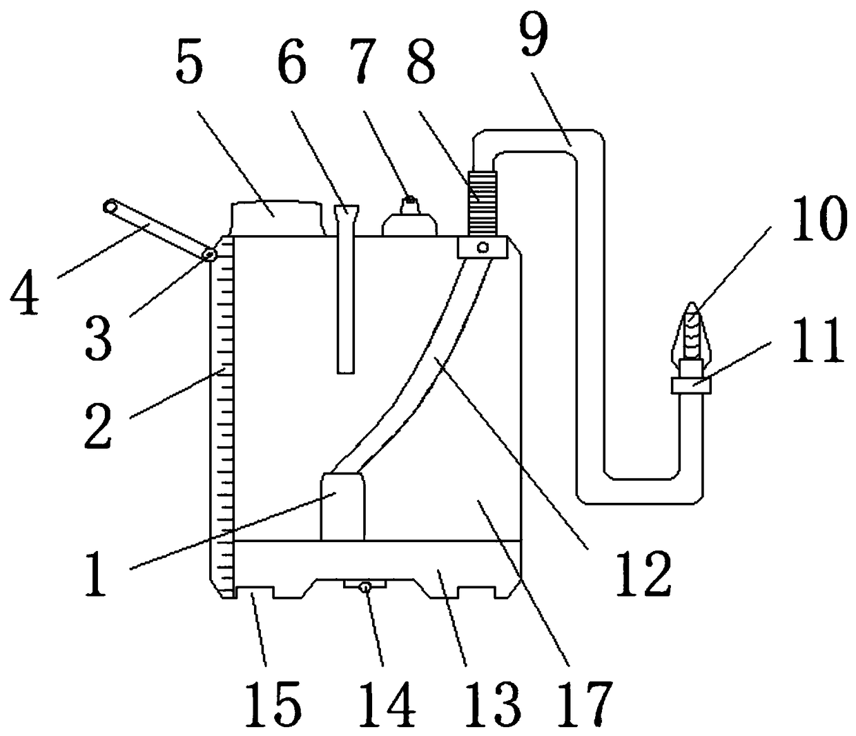
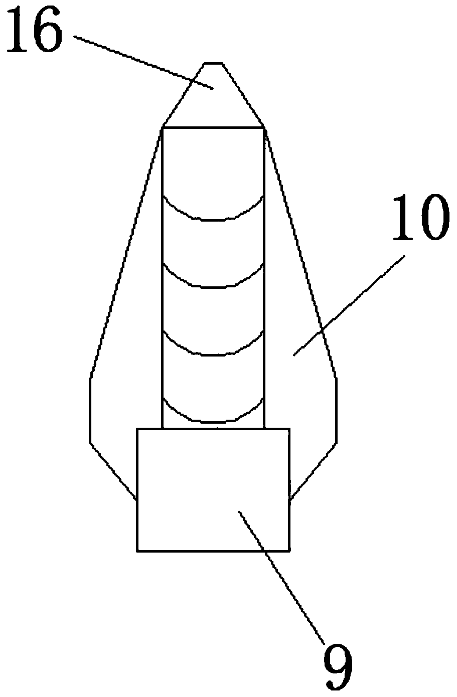
[0017] like Figure 1-2 As shown, a drainage device for breast surgery includes a bottle body 17, a water injection port 5 is provided at one end of the top end of the bottle body 17, and a ventilation tube 6 is provided at the top middle part of the bottle body 17, and the bottle body 17 The other end of the top end is sleeved with a drainage tube 9 through a sealing tube 8, a negative pressure regulating valve 7 is fixedly connected between the drainage tube 9 and the ventilation tube 6, and an antibacterial collar 11 is sleeved on the surface of one end of the drainage tube 9 One end of the drainage tube 9 is fixedly connected with a joint 10, and one end of the joint 10 is provided with a beak 16, and the bottom end of the sealing tube 8 is provided with a built-in drainage tube 12, and the bottom end of the built-in drainage tube 12 A drainage valve port 1 is provided, and the top of one side of the bottle body 17 is connected with a handle 4 through the rotation of the rocker 3. One side of the surface of the bottle body 17 is embedded with a water level monitoring scale line 2, and the bottle body 17 Limiting grooves 15 are opened at both ends of the bottom end of the bottle body 17, and the middle part of the bottom end of the bottle body 17 is fixedly connected with a fastening device 14. The inner bottom end of the bottle body 17 is provided with a backing plate 13, and the drainage valve port 1 is provided with on the surface of the backing plate 13.
[0018] Wherein, the material of the drainage tube 9 is natural rubber, the pipe diameter of the drainage tube 9 is 7-9mm, and the drainage tube 9 is a transparent structure.
[0019] Wherein, the pointed mouth 16 has a needle-shaped structure, the surface of the pointed mouth 16 is provided with an inclination angle of 45 degrees, and the material of the pointed mouth 16 is polyethylene.
[0020] Wherein, the sealing tube 8 is a spiral structure, the sealing tube 8 is a detachable structure, the material of the sealing tube 8 is silica gel, and the sealing tube 8 made of silica gel can be adjusted conveniently.
[0021] Wherein, the limiting groove 15 is a rectangular groove structure, and the limiting groove 15 is symmetrically distributed with respect to the fastening device 14 .
[0022] Wherein, the ventilation tube 6 is a detachable structure, and the ventilation tube 6 runs through the inside of the bottle body 17 , and the material of the ventilation tube 6 is PVC polyvinyl chloride, and the gas conversion can be performed through the ventilation tube 6 .
[0023] Wherein, the inside of the fastening device 14 is provided with threads, and the fastening device 14 is arranged at the center of the bottle body 17 .
[0024] It should be noted that the present invention is a drainage device for breast surgery. During use, the lifting handle 4 is conveniently taken by the rotation of the rocker 3, and the invention is snapped into the fixed area through the limiting groove 15. Fix the thread inside the fastening device 14, then insert the pointed mouth 16 into the breast, operate the negative pressure regulating valve 7 to pass through, the liquid or gas inside the breast will flow into the drainage tube 9 through the joint 10, and then flow into the tube through the sealing tube 8 The inside of the built-in drainage tube 12 enters the bottle body 17 through the drainage valve port 1. When the negative pressure inside the mammary gland is restored, the liquid inside the bottle body 17 is sucked onto the backing plate 13, thereby forming negative pressure water and preventing air from entering the mammary gland. , the conversion of gas can be carried out through the vent pipe 6, the liquid capacity situation inside the bottle body 17 can be checked by observing the water level monitoring scale line 2, and the inside of the bottle body 17 can be filled with water through the water injection port 5. When the bottle body 17 is to be cleaned, It can be cleaned through the water injection port 5.
[0025] The basic principles and main features of the present invention and the advantages of the present invention have been shown and described above. Those skilled in the industry should understand that the present invention is not limited by the above-mentioned embodiments, and what described in the above-mentioned embodiments and the description only illustrates the principles of the present invention, and the present invention will also have other functions without departing from the spirit and scope of the present invention. Variations and improvements are possible, which fall within the scope of the claimed invention. The protection scope of the present invention is defined by the appended claims and their equivalents.

PUM

PropertyMeasurementUnit
Diameter7.0 ~ 9.0mm

Description & Claims & Application Information

We can also present the details of the Description, Claims and Application information to help users get a comprehensive understanding of the technical details of the patent, such as background art, summary of invention, brief description of drawings, description of embodiments, and other original content. On the other hand, users can also determine the specific scope of protection of the technology through the list of claims; as well as understand the changes in the life cycle of the technology with the presentation of the patent timeline. Login to view more.

Similar technology patents

Stator assembly for asynchronous motor and method for making same

InactiveCN101043154AEasy to windreasonable design
Owner:GUANGDONG WELLING ELECTRIC MACHINE MFG

Classification and recommendation of technical efficacy words

Why Eureka
Try Eureka