Illumination system employing array of microprisms

A technology of microprisms and lighting components, applied in the field of lighting applications and lighting systems, can solve the problems of lack of directional control of light output, low input efficiency, uneven distribution of light, etc.

Inactive Publication Date: 2002-11-27
ALLIEDSIGNAL INC
View PDF1 Cites 0 Cited by
  • Summary
  • Abstract
  • Description
  • Claims
  • Application Information

AI Technical Summary

Problems solved by technology

Typical problems encountered with collimated light sources include: (1) uneven distribution of light; (2) lack of directional control of light output; (3) inefficiency of collimated light output relative to non-collimated light input; (4) Lack of effective collimated light source in compact design or narrow profile

Method used


Image

  • Illumination system employing array of microprisms
  • Illumination system employing array of microprisms
  • Illumination system employing array of microprisms

Examples


Embodiment Construction

[0027] DETAILED DESCRIPTION OF THE PREFERRED EMBODIMENT

[0028] Those skilled in the art will better understand the preferred embodiments of the present invention with reference to the above illustrations. The preferred embodiments of the invention shown in the drawings are not intended to be exhaustive or to limit the invention to the precise forms disclosed. They were chosen to describe or best explain the principles of the invention and its applicability, thereby enabling others skilled in the art to best utilize the invention.

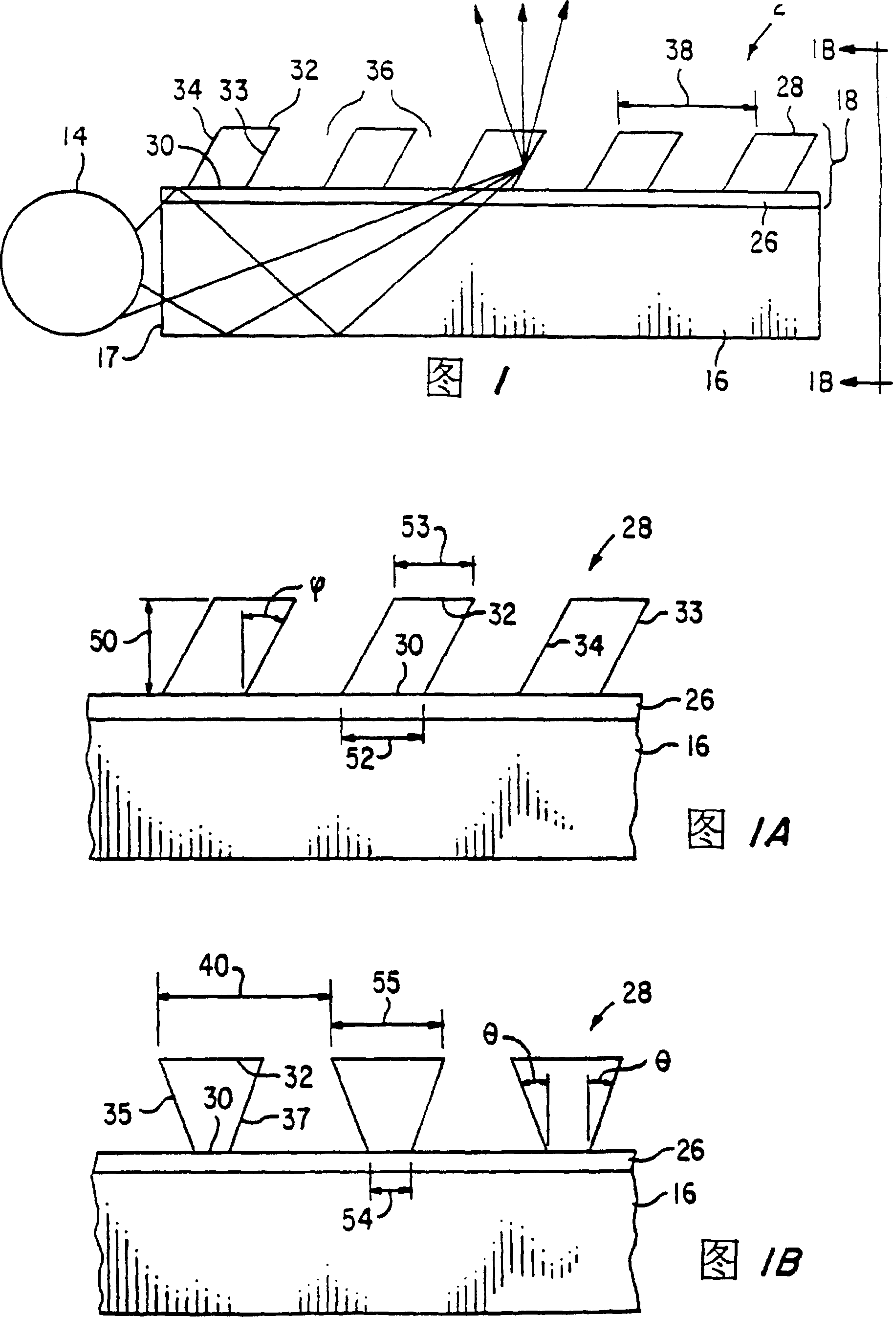
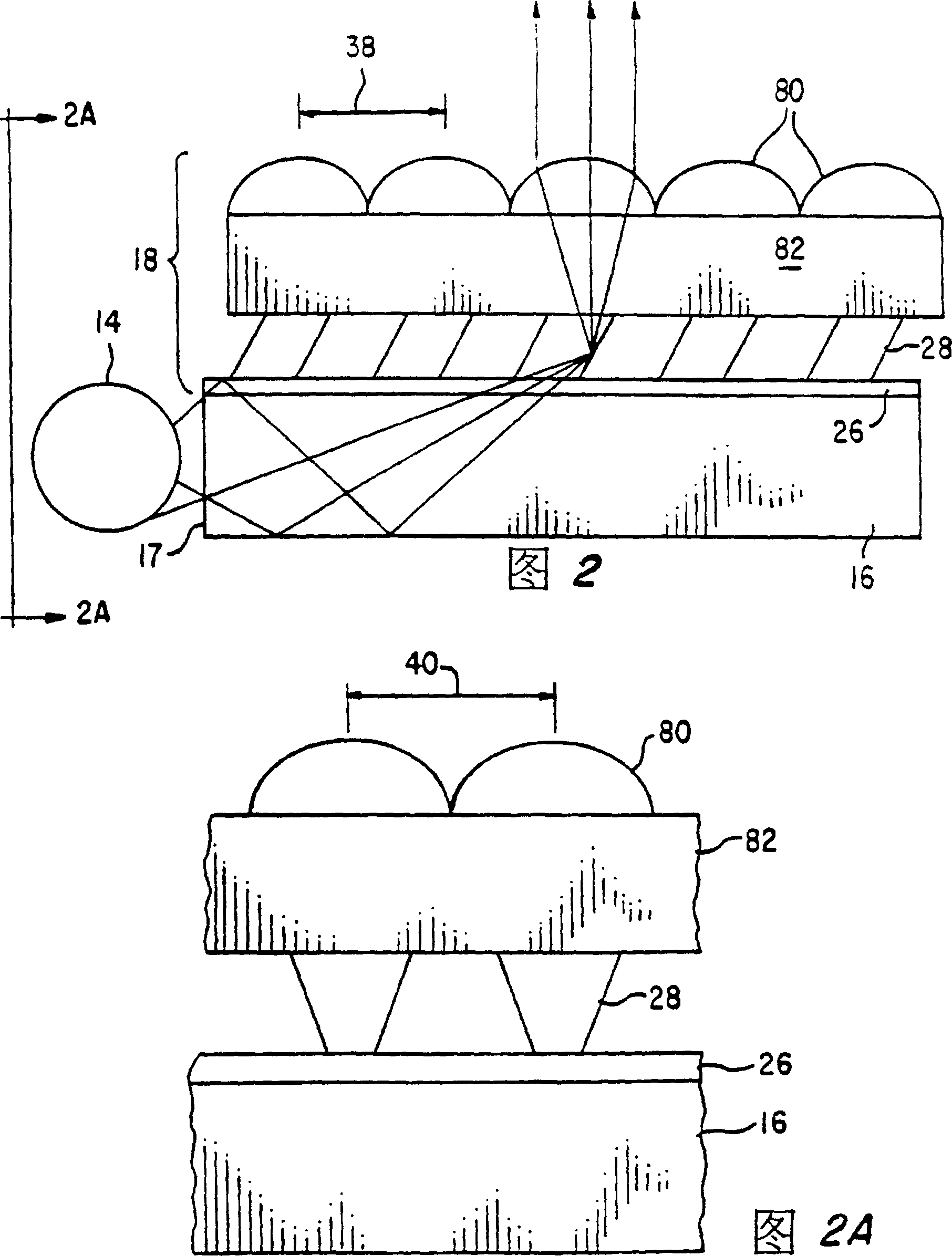
[0029] A preferred embodiment of the present invention is shown in Figures 1, 1A and 1B. An illumination system denoted by numeral 2 comprises: a light generating means 14, a waveguide 16 having a light receiving surface 17 and transparent reflecting means 18 in contact with the waveguide 16. Examples of useful light generating devices 14 include lasers, fluorescent tubes, light emitting diodes, incandescent lamps, sunlight, and the like. The w...


PUM


Abstract

An optical illumination assembly including a waveguide for receiving light generated by a diffuse light source and transmitting the light by total internal reflection. Attached to one side of the waveguide is a group of microprisms, the light incident surface of each microprism is parallel to the light exit surface, and there is a certain oblique angle between at least two side walls and the normal direction of the waveguide surface, thus, the light It is separated from the waveguide, reflected by the inclined side wall, and emitted from the microprism as a spatially directional light source. If a group of macro lenses are arranged to receive the output light of the micro prisms, the light emitted by the macro lenses becomes a substantially collimated light source. The optical illumination assembly is advantageous for any application requiring non-scattering or substantially collimation that is energy efficient and contained within a low profile assembly.

Description

[0001] Cross-references to related applications [0002] This application is a continuation-in-part of U.S. Serial No. 08 / 149,219, filed January 11, 1994, entitled "Backlighting Apparatus Using an Array of Microprisms." Background of the invention [0003] In general, the present invention relates to an optical illumination system for producing collimated light, thereby achieving a relatively high light transmission. More specifically, the present invention relates to an illumination system comprising a plurality of optical microprisms and macromirrors for redirecting light from a non-collimated source, or separately or in combination to form a non-scattering or substantially collimated light source. Straight light output. [0004] Many optical and lighting applications require the generation of a non-diffuse or collimated light source for efficient light output. Typical problems encountered with collimated light sources include: (1) uneven distribution of light; (2) lack of...

Claims


Application Information

Patent Timeline
Patent Type & Authority Patents(China)
IPC IPC(8): F21V8/00F21V5/02G02B6/00
CPCF21V5/02F21Y2103/00G02B6/0053G02B6/0001
Inventor S·M·齐默尔曼J·C·施伟延K·W·比森J·候
Owner ALLIEDSIGNAL INC
Why Eureka
Try Eureka