Active radial magnetic bearing with a yoke coil

A magnetic bearing and radially protruding technology, applied in the field of radial magnetic bearings, can solve the problems of low force density and disadvantages, and achieve the effect of increased force density

Active Publication Date: 2019-03-22
麦克森国际股份公司
View PDF21 Cites 3 Cited by
  • Summary
  • Abstract
  • Description
  • Claims
  • Application Information

AI Technical Summary

Problems solved by technology

However, it has a very large winding head, which is not conducive to force development
Therefore, the force density is relatively low

Method used


Image

  • Active radial magnetic bearing with a yoke coil
  • Active radial magnetic bearing with a yoke coil
  • Active radial magnetic bearing with a yoke coil

Examples


Embodiment Construction

[0035] The same components are denoted by the same reference numerals for the following embodiments. If a figure contains a reference number which is not discussed in more detail in the relevant figure description, reference is made to the preceding or following figure description.

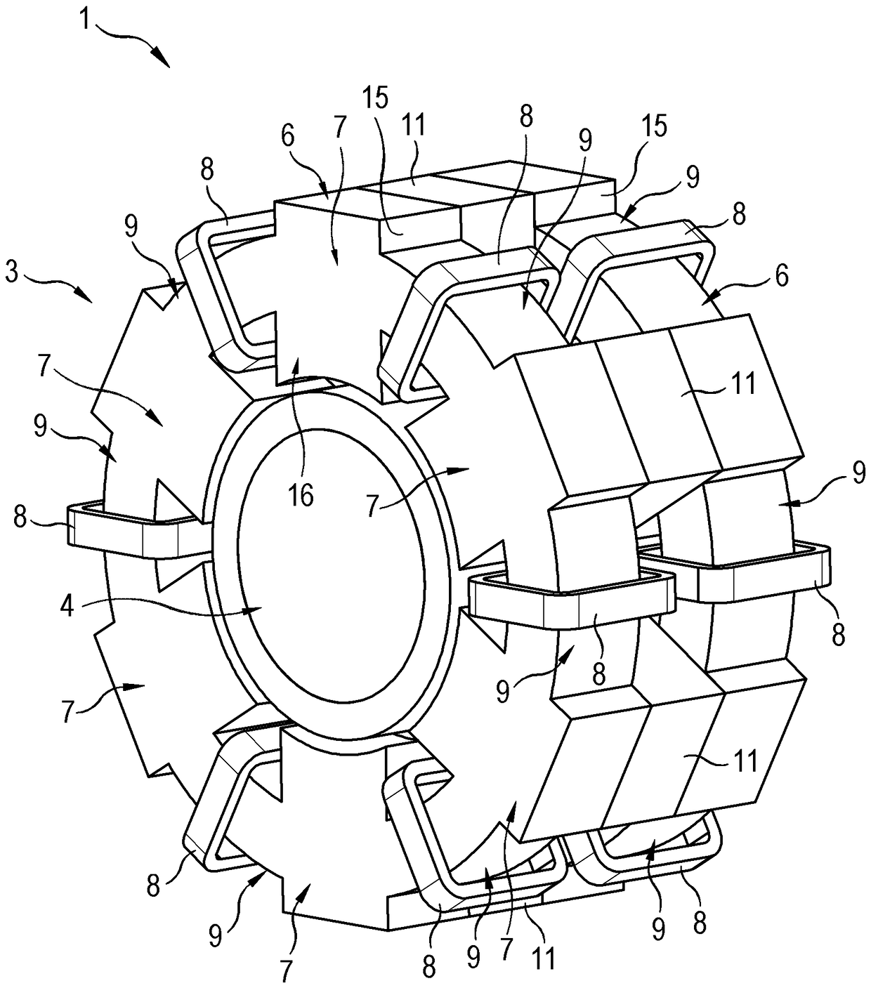
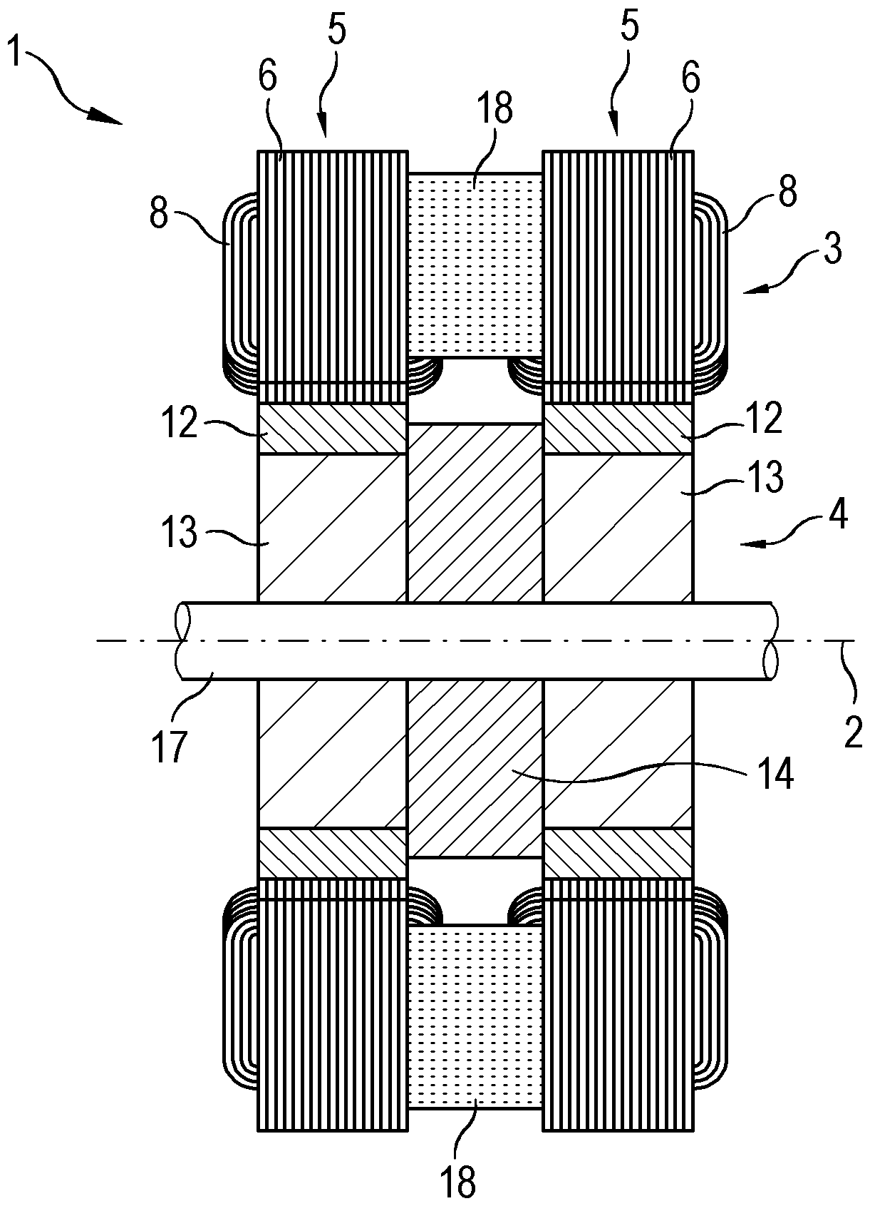
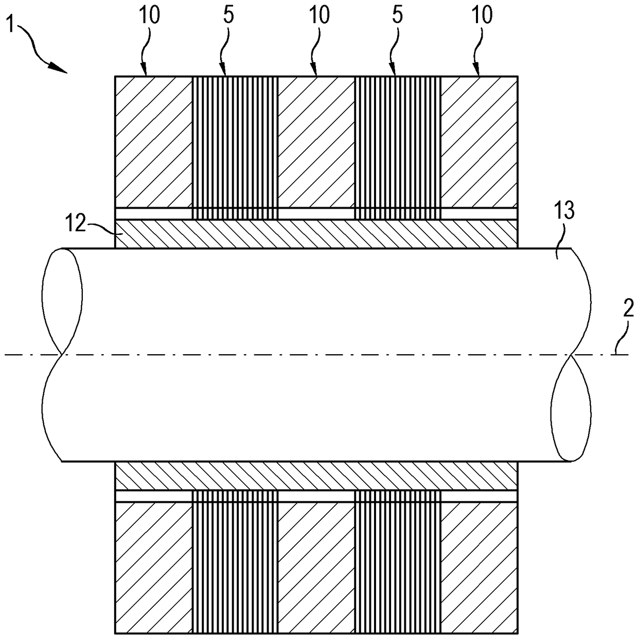
[0036] Figure 1 to Figure 3 A first embodiment of a radial magnetic bearing 1 according to the invention is shown. The magnetic bearing comprises an outer stator 3 and an inner rotor 4 . The stator 3 and the rotor 4 are arranged coaxially with each other. They are therefore both constructed substantially rotationally symmetrically about the common axis 2 of the magnetic bearings.

[0037]as in figure 2 As particularly shown in , the stator 3 includes two stator assemblies 5 spaced apart from each other in the axial direction. Each of the two stator assemblies 5 includes a soft magnetic core 6 . In the illustrated embodiment, the soft magnetic cores are each configured as a soft magnetic la...


PUM


Abstract

A radial magnetic bearing includes an axis, a stator and a rotor, where the stator includes at least two stator assemblies axially spaced from one another, where each of the stator assemblies includesa magnetically soft core, where at least one of the stator assemblies comprises one said magnetically soft core with several radially projecting teeth arranged distributed in the circumferential direction, and several coils likewise arranged distributed in the circumferential direction, and where two respective teeth of the magnetically soft core that are successive in the circumferential direction are connected to each other by way of a connecting section of the core. The magnetic bearing includes a permanent magnet assembly disposed axially between the two magnetically soft cores. At leastone said stator arrangement with several coils arranged distributed in the circumferential direction, the magnetically soft core of which includes several radially projecting teeth arranged distributed in the circumferential direction, is embodied such that one of the respective connecting sections is wound with one of the respective coils.

Description

technical field [0001] The invention relates to a radial magnetic bearing according to the preamble of independent claim 1 . Background technique [0002] Common radial magnetic bearings include shafts, stators and rotors. The stator and the rotor are arranged coaxially with respect to each other and with respect to the axis of the magnetic bearing. The stator includes at least two axially spaced stator assemblies. Each stator assembly includes one said soft magnetic core, wherein at least one stator assembly includes one said soft magnetic core, said soft magnetic core has a number of radially protruding teeth distributed in the circumferential direction and also in the circumferential direction distributed coils. Two corresponding teeth successive in the circumferential direction of the soft magnetic core are connected to each other by a connection section of the core. The magnetic bearing also includes a permanent magnet assembly axially disposed between the two soft ...

Claims


Application Information

Patent Timeline
IPC IPC(8): F16C32/04
CPCF16C32/0459F16C32/0465F16C2202/40F16C32/0461F16C32/048F16C32/044H01F7/081H01F27/24H01F27/306
Inventor J.克雷赫尔
Owner 麦克森国际股份公司
Why Eureka
Try Eureka