Device and method for monitoring vertical displacement of bridge body of multi-section constructed bridge

A vertical displacement and monitoring device technology, which is applied in the fields of inspection and maintenance, management and maintenance, and bridge structure monitoring, can solve the problems of reference liquid level fluctuations, reduce liquid evaporation speed, uneconomical and energy-saving structural design complexity, etc., and achieve comprehensive measurement , high-precision effect

Pending Publication Date: 2019-03-22
CCCC ROAD & BRIDGE SPECIAL ENG
View PDF0 Cites 5 Cited by
  • Summary
  • Abstract
  • Description
  • Claims
  • Application Information

AI Technical Summary

Problems solved by technology

For the constant maintenance of the reference liquid level in the long-term monitoring process, there are mainly: (1) attaching a layer of silicone oil, liquid paraffin and other floating measures on the liquid surface to reduce the evaporation rate of the liquid; (2) setting an automatic water replenishment device, but the existing automatic water replenishment device Both include long-term work of pumping equipment that requires external power, which is neither economica

Method used


Image

  • Device and method for monitoring vertical displacement of bridge body of multi-section constructed bridge
  • Device and method for monitoring vertical displacement of bridge body of multi-section constructed bridge
  • Device and method for monitoring vertical displacement of bridge body of multi-section constructed bridge

Examples


Example Embodiment

[0032] The present invention will be further described in detail below with reference to the accompanying drawings, so that those skilled in the art can implement it with reference to the text of the description.

[0033] It should be noted that the experimental methods described in the following embodiments are conventional methods unless otherwise specified, and the reagents and materials, unless otherwise specified, can be obtained from commercial sources; in the description of the present invention, The terms "horizontal", "vertical", "upper", "lower", "front", "rear", "left", "right", "vertical", "horizontal", "top", "bottom", The orientation or positional relationship indicated by "inner" and "outer" is based on the orientation or positional relationship shown in the drawings, which is only for the convenience of describing the present invention and simplifying the description, and does not indicate or imply that the device or element referred to must have The specific orie...


PUM


Abstract

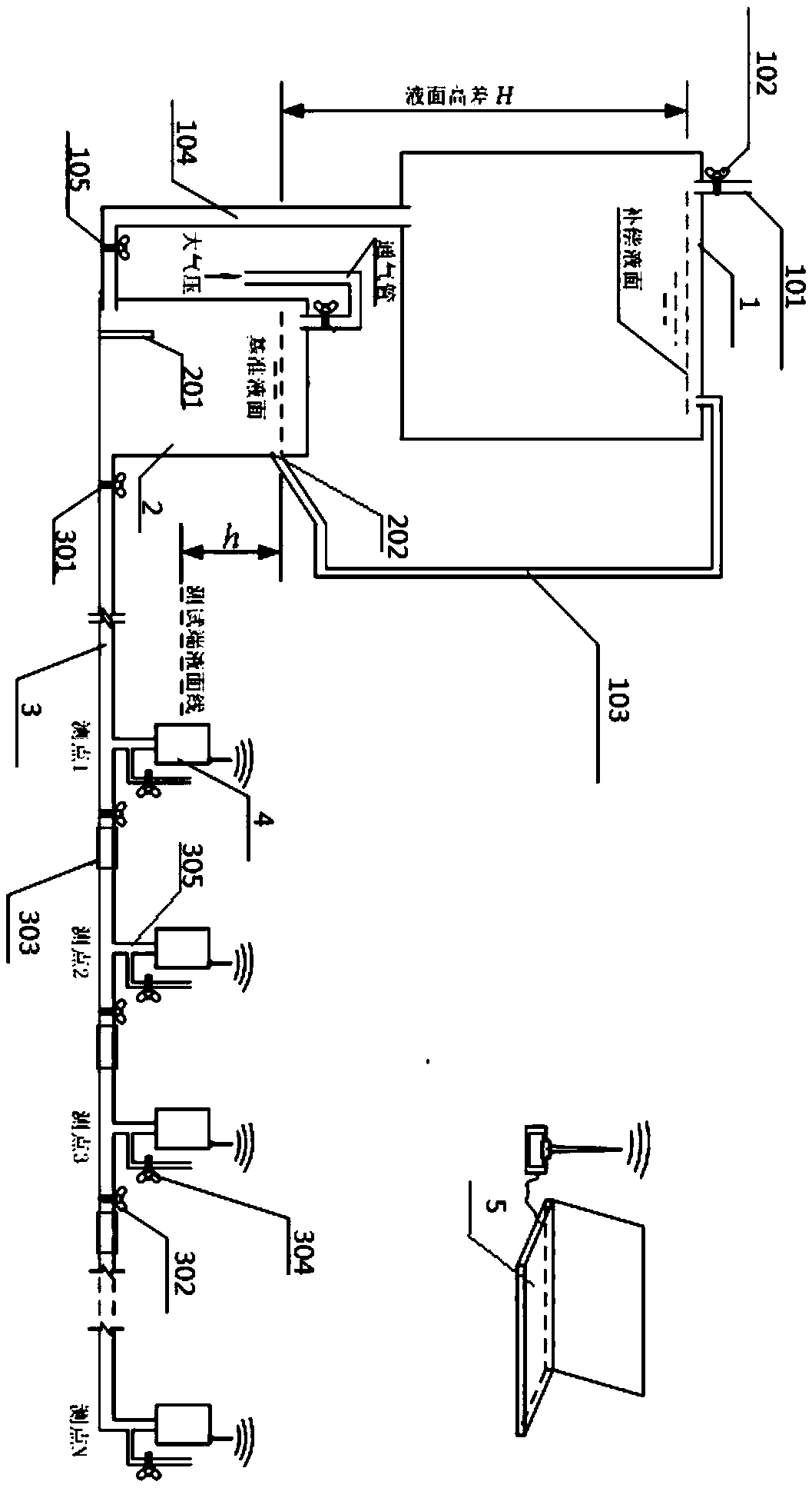
The invention discloses a device and method for monitoring the vertical displacement of a bridge body of a multi-section constructed bridge. The device comprises a standard liquid tank, a liquid supplementing tank, a liquid surface control pipe, a liquid supplementing pipe, a liquid communicating pipe and a displacement sensor, wherein the position, close to the top, of the side wall of the standard liquid tank is provided with a liquid surface control hole, the standard liquid tank is filled with liquid which is flush with the top edge of the liquid surface control hole, a ventilating pipe with a valve is arranged on the top of the standard liquid tank, the liquid supplementing tank is filled with liquid, the bottom surface elevation of the liquid supplementing tank is not lower than thetop surface elevation of the standard liquid tank, one end of the liquid surface control pipe is connected with the top of the liquid supplementing tank, the other end of the liquid surface control pipe is connected with the liquid surface control hole, the two ends of the liquid supplementing pipe are connected with the bottom of the standard liquid tank and the bottom of the liquid supplementingtank respectively, one end of the liquid communicating pipe is communicated with the lower portion of the standard liquid tank, the end, close to the standard liquid tank, of the liquid communicatingpipe is provided with a working valve, and the displacement sensor is connected with the standard liquid tank through the liquid communicating pipe. The device and method are suitable for automatically monitoring the vertical displacement of the bridge body in the bridge multi-section construction period and also suitable for automatically monitoring the vertical displacement for a long time after the structure is completed.

Description

technical field [0001] The invention relates to the fields of bridge structure monitoring, detection and maintenance, management and maintenance. More specifically, the present invention relates to a device and method for monitoring the vertical displacement of a girder body of a bridge constructed in sections. Background technique [0002] With the progress of our country's economy and society in recent years, bridge construction has developed vigorously, and the number of long-span bridges that have been built or are under construction is increasing day by day. , Suspension bridges have been used on a large scale. In order to ensure the safety of this type of bridge structure during operation, displacement monitoring equipment is installed or planned to be installed after the bridge is completed. For the safety of its construction period, the artificial periodic measurement method based on the level (total station) is still used alone at present, which has the disadvantag...

Claims


Application Information

Patent Timeline
IPC IPC(8): G01B21/02G01M5/00
CPCG01B21/02G01M5/0008
Inventor 朱世峰曾松亭周志祥吴海军朱慈祥周华威陈泽刘昂杨曦王伟赵顺清
Owner CCCC ROAD & BRIDGE SPECIAL ENG
Why Eureka
Try Eureka