
Portable microelectronic alternate current counting device testing table

A kind of microelectronics and portable technology, applied in the field of electronics, can solve the problems of no test bench, no movement, complicated operation, etc., and achieve the effect of quality, small size, practical function and convenient use

Active Publication Date: 2019-03-22
QLT RAILWAY EQUIP FACTORY
View PDF4 Cites 2 Cited by
  • Summary
  • Abstract
  • Description
  • Claims
  • Application Information

AI Technical Summary

Problems solved by technology

[0003] The existing routine maintenance test needs to disassemble the code box and sending box, replace them with spare parts, and then send them to the maintenance station for inspection and repair. Most of the local railways, factories and mines special-purpose lines for microelectronic AC counter equipment test benches are expensive and difficult to operate. It is complicated and needs to be equipped with professionals. Therefore, considering the cost issue, the test bench is not configured. If it is broken, a new code box and code sending box will be replaced. Usually, a station needs to be equipped with 2 code boxes and 4 code sending boxes. It is necessary to spare a corresponding number of spare parts. According to the experience in the industry, within a 15-year life cycle of a station signal equipment, it needs to spend nearly 70,000 yuan on spare parts for the maintenance of microelectronic AC counter equipment, and configure the existing test bench. A professional operator and inspector needs to be deployed, and a certain amount of spare parts needs to be allocated to a station for replacement. Therefore, within the 15-year life cycle of the equipment, it is necessary to spend millions of yuan on the maintenance of the microelectronic AC counter equipment.
[0004] In addition, the existing test benches are large in size and heavy, and can only be used fixedly and cannot be moved, so that on-site testing cannot be carried out

Method used


Image

  • Portable microelectronic alternate current counting device testing table
  • Portable microelectronic alternate current counting device testing table

Examples


Embodiment Construction

[0019] In order to make the technical means, creative features, objectives and effects achieved by the present invention easy to understand, the present invention will be further explained below in conjunction with specific embodiments.

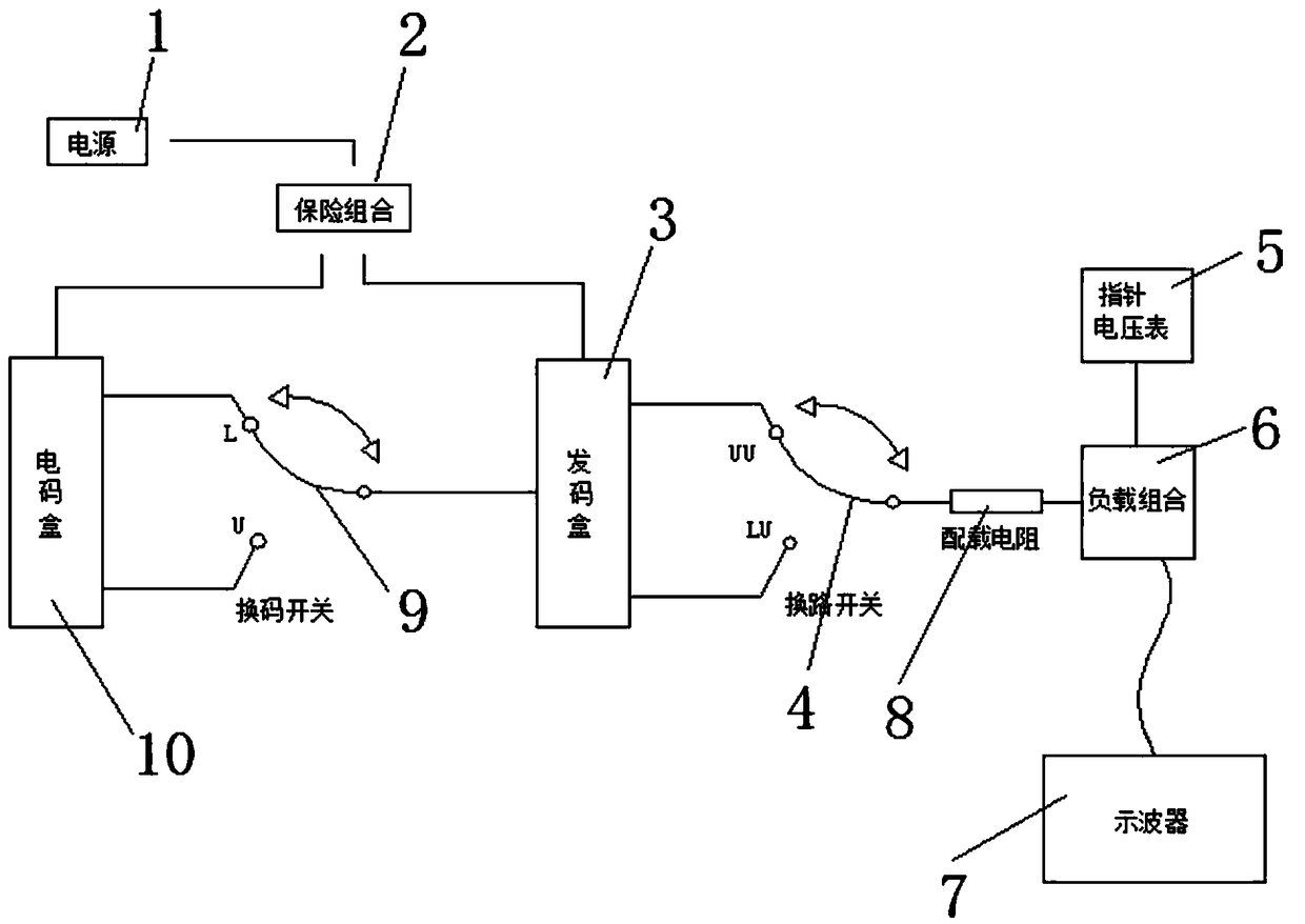
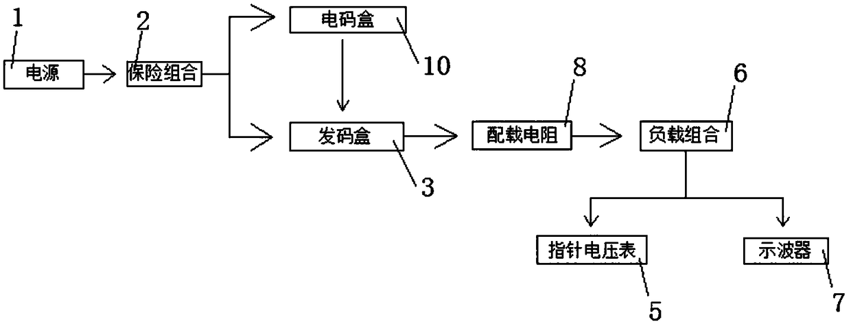
[0020] Such as Figure 1-2 As shown, a portable microelectronic AC counter material test bench includes a fuse combination 2 and a load combination 6. The upper end of the fuse combination 2 is provided with a power source 1, and both sides of the lower end of the fuse combination 2 are electrically connected with electrical codes. The code box 10 and the code sending box 3 are respectively provided with "L" and "U" on the upper and lower ends of one side surface of the code box 10, and an escape switch 9 is electrically connected to one side of the code sending box 3. The end of the code switch 9 cooperates with "L" or "U" to switch and connect. The code transmitting box 3 and the code box 10 are electrically connected to each other through the...


PUM


Abstract

The invention discloses a portable microelectronic alternate current counting device testing table. The portable microelectronic alternate current counting device testing table comprises a safety combination and a load combination, wherein the upper end of the safety combination is provided with a power source, both sides of the lower end of the safety combination are electrically connected with acode box and a code delivery box respectively, the upper end and the lower end of one surface of the code box are provided with L and U, one side surface of the code delivery box is electrically connected with a code changing switch, the tail end of the code changing switch is matched with and connected in a switching mode with the L or U, the code delivery box and the code box are electrically connected with the code switching switch, and the upper end and the lower end of the other surface of the code delivery box are provided with UU and LU; one side surface of the load combination is electrically connected with a circuit-changing switch. The entire portable microelectronic alternate current counting device testing table is low in manufacturing price, smaller in weight and size compared with traditional equipment, simple in operation and capable of performing field testing at any time without professionals.

Description

Technical field [0001] The present invention relates to the field of electronic technology, in particular to a portable microelectronic AC counter material test bench. Background technique [0002] The coding of microelectronic AC counting plays a key role in preventing trains from overspeeding and entering the signal machine. Because of its relatively low price and simple maintenance, it is widely used by many local railways and special lines for factories and mines. [0003] The existing routine maintenance test requires the code box and the sending box to be removed, replaced with spare parts, and sent to the inspection and repair station for inspection and repair. In most places, the microelectronic AC counter material test bench for railways and factories and mines is expensive. It is complicated and requires the deployment of professionals. Therefore, considering the cost issue, the test bench is not configured. If it is broken, a new code box and code sending box are replace...

Claims


Application Information

Patent Timeline
Patent Type & Authority Applications(China)
IPC IPC(8): G01R31/00
CPCG01R31/00G01R19/0084G01R13/00G01R1/30
Inventor 韩伟
Owner QLT RAILWAY EQUIP FACTORY
Learn More