Supercharge Your Innovation With Domain-Expert AI Agents!

Fibre-optical unit positioning apparatus for astronomy spectrotelescope

A technology of optical fiber positioning and unit device, which is applied in the production field of the focal plane system of astronomical spectroscopic telescopes. It can solve problems such as complex structure and unsuitable density of distribution points, and achieve good receiving efficiency.

Inactive Publication Date: 2002-11-27
UNIV OF SCI & TECH OF CHINA
View PDF4 Cites 1 Cited by
  • Summary
  • Abstract
  • Description
  • Claims
  • Application Information

AI Technical Summary

Problems solved by technology

Although this method has the advantage of convenient adjustment, its structure is complex, and each receiving end has an optical fiber dragged on the substrate, so the distribution density should not be too large. error, generally only applicable to small fiber optic substrates

Method used


Image

  • Fibre-optical unit positioning apparatus for astronomy spectrotelescope
  • Fibre-optical unit positioning apparatus for astronomy spectrotelescope
  • Fibre-optical unit positioning apparatus for astronomy spectrotelescope

Examples


Embodiment Construction

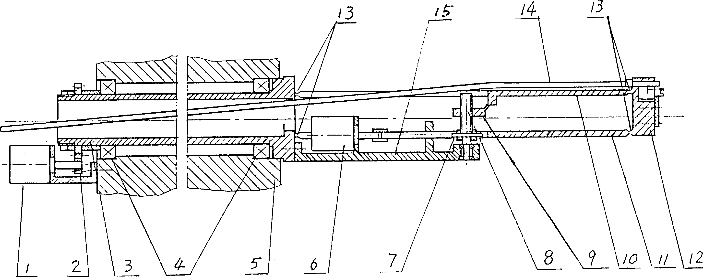
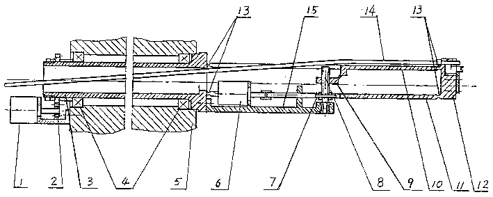
[0012] figure 1 Among them, (1) is the rotation control motor A, (2) is the rotation reduction gear set A, (3) is the hollow shaft, (4) is the bearing, (5) is the focus plate, (6) is the translation control motor B, (7) is translation reduction gear set B, (8) is screw rod, (9) is nut, (10), (11) are upper and lower parallel plate, (12) is connecting rod plate, (13) is flexible hinge , (14) optical fiber, (15) is a fixed support.

[0013] From figure 1 It can be seen from the figure that when the rotary control motor A (1) moves, the gear fixed on the hollow shaft is rotated through the rotary reduction gear set A, so that the hollow shaft (3) is rotated. The hollow shaft is installed on the focus plate (5) and supported by the left and right bearings (4). In actual use, a stepping motor can be selected to make it drive forward and reverse according to the control pulse requirements, so that the hollow shaft can operate within ±180° rotation. When the translation control m...


PUM


Abstract

The present invention relates to a position-fixing device of optical fibre on the focal plane of astronomical spectrotelescope. It is formed of combination of gyroscopic motion mechanism and radial traslational motion mechanism, in which the former is driven by control motor via a reducing driving mechanism, and can be turned in the range of plus or minus 180 deg. and the latter is driven by control motor via a parallelogram translational motion device, so that it can make the connecting rod board used for installing optical fibre head implement radial translational motion in hollow shaft to implement polar coordinate position-fixing operation of optical fibre head. When said invented position-fixing device is used in large-size telescope, several unit devices can be assembled on same focal plane, so that it can be used to observe several asters at the same time, and can be easily and quickly regulated.

Description

technical field [0001] The invention relates to the manufacture of a focal plane system of an astronomical spectrum telescope, in particular to an optical fiber positioning device on the focal plane. Background technique [0002] Optical fiber is the light-receiving element of astronomical spectroscopic telescope. During actual observation, the optical fiber receiving head is aimed at the position of the star image of the celestial body to collect the light of the star image and transmitted to the spectrometer through the optical fiber. Due to the large sky area and the large number of celestial bodies, and the limited aperture and focal area of ​​the telescope, a telescope can only observe a part of the sky area at a time. If you need to change the observation sky area, you need to adjust the position of the optical fiber receiving head so that it corresponds to the position of the celestial body and star image in the new sky area. When the area of ​​the focal plane is fi...

Claims


Application Information

Patent Timeline
IPC IPC(8): G02B7/28G02B23/12G02B23/14
Inventor 邢晓正杜华生胡红专翟超朱冰石德秀
Owner UNIV OF SCI & TECH OF CHINA
Features
  • R&D
  • Intellectual Property
  • Life Sciences
  • Materials
  • Tech Scout
  • Unparalleled Data Quality
  • Higher Quality Content
  • 60% Fewer Hallucinations
Learn More