An insulator structure for protecting vacuum tubes

A technology of vacuum tubes and insulators, applied in high-voltage air circuit breakers, high-voltage/high-current switches, electrical components, etc., can solve the problems of high performance requirements, reliability failures, and application of thermal stress of vacuum tubes, and achieve processability and economy. The effect of highlighting, prolonging service life and improving reliability

Active Publication Date: 2020-08-25
BEIJING CED RAILWAY ELECTRIC TECH
View PDF6 Cites 0 Cited by
  • Summary
  • Abstract
  • Description
  • Claims
  • Application Information

AI Technical Summary

Problems solved by technology

The commonly used technical method nowadays is to directly pour silicone rubber between the vacuum tube and the insulator to solve the problem of external high-voltage insulation between the poles of vacuum circuit breakers. The stress is within the tolerable range of the vacuum tube, but it has high requirements on the performance of the vacuum tube, and at the same time, it also poses a certain risk of failure for its long-term application reliability

Method used


Image

  • An insulator structure for protecting vacuum tubes
  • An insulator structure for protecting vacuum tubes
  • An insulator structure for protecting vacuum tubes

Examples


specific Embodiment

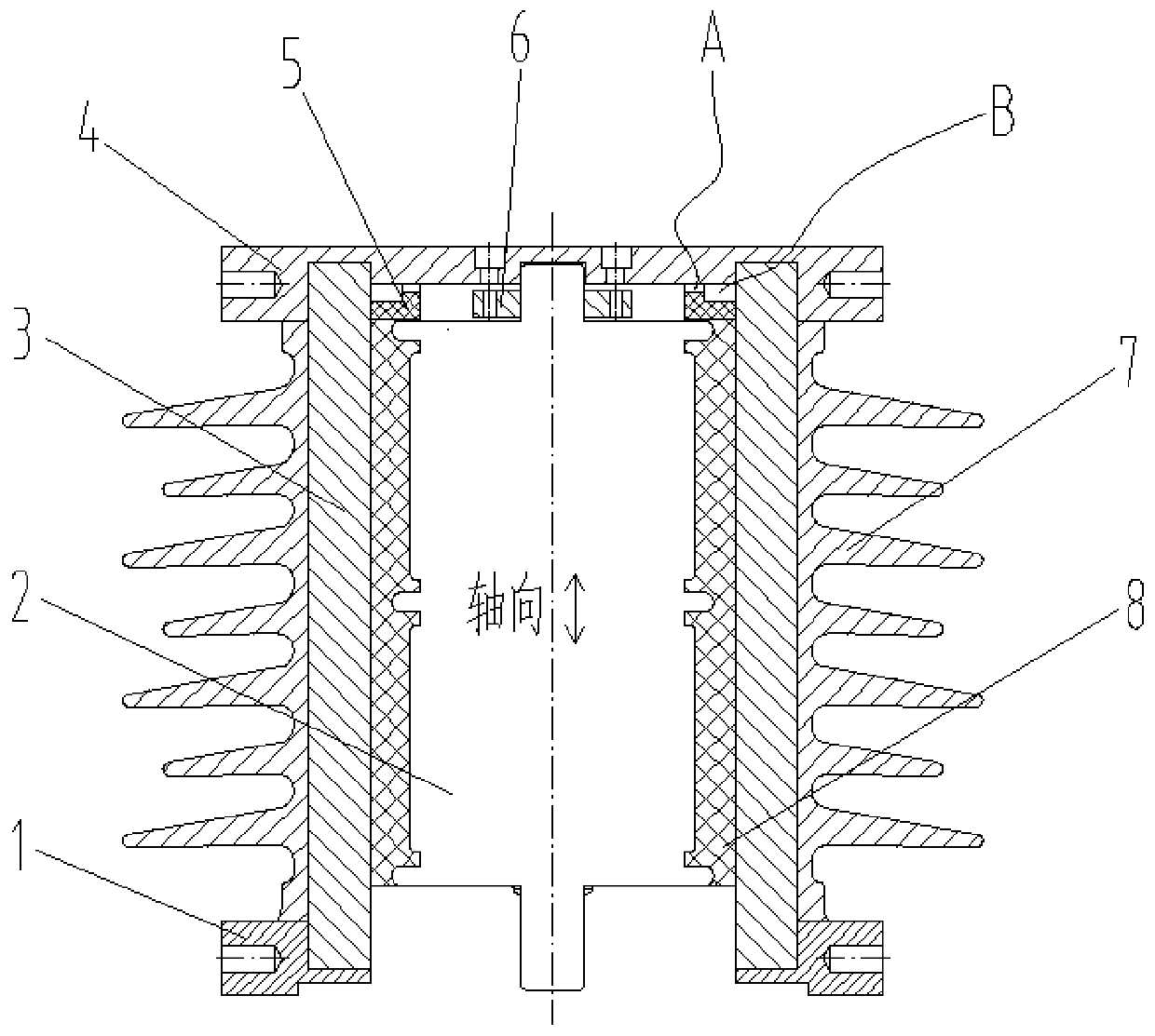
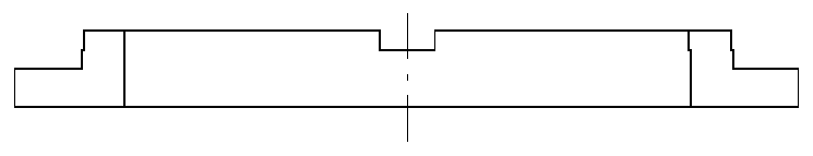
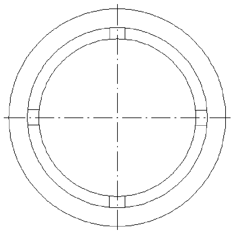
[0027] Such as Figure 1-3 As shown, the insulator structure for protecting the vacuum tube of the present invention includes a lower flange 1, a vacuum tube 2, an epoxy resin core tube 3, an upper flange 4, a sealing ring 5, a compression ring 6, an insulating shed 7 and a silicone rubber 8. Among them, the epoxy resin core tube 3 is covered with an insulating shed 7 on the outside, and the two ends are respectively glued to the upper flange 4 and the lower flange 1, and the vacuum tube 2 is installed in the middle of the inner cavity of the epoxy resin core tube 3. The ring 6 is fixed to the upper flange 4, and the sealing ring 5 matching the inner wall of the epoxy resin core tube 3 is pressed between the vacuum tube 2 and the upper flange 4, and the silicone rubber 8 is poured on the epoxy resin core tube 3, the vacuum tube In the annular cavity between 2 and sealing ring 5, the above-mentioned components together constitute an insulator structure. In this embodiment, the...


PUM

PropertyMeasurementUnit
Shore hardnessaaaaaaaaaa

Abstract

The invention discloses an insulator structure for protecting a vacuum tube. The insulator structure comprises a lower flange, a vacuum tube, an epoxy resin core tube, an upper flange, a sealing ring,a pressing ring, insulating sheds and silicone rubber; the exterior of the epoxy resin core tube is coated with the insulating sheds; two ends of the epoxy resin core tube are respectively sealed andglued with the upper flange and the lower flange; the vacuum tube is installed in the middle of the inner cavity of the epoxy resin core tube, and is fixed to the upper flange through the pressing ring; the sealing ring matched with the inner wall of the epoxy resin core tube is installed between the vacuum tube and the upper flange in a pressed manner; the silicone rubber is poured in an annularcavity between the epoxy resin core tube, the vacuum tube and the sealing ring; and the above components jointly constitute the insulator structure. The insulator structure of the invention has the advantages of simple and scientific structure, prominent techniques and high economical efficiency. With the sealing ring of an ingenious structure adopted, the force bearing characteristics of the vacuum tube can be changed; and the constant-temperature casting process of the silicone rubber realized, the use environment of the vacuum tube can be greatly improved, and a protection function can berealized.

Description

technical field [0001] The invention relates to a high-voltage electrical appliance and a high-voltage insulating device, in particular to an insulator structure for protecting a vacuum tube. Background technique [0002] In the field of 25kV main line railways, whether it is a locomotive or an EMU, the vacuum circuit breaker is an indispensable main switch of the high-voltage system, and is also an important executive component of the locomotive or EMU vehicle control and protection logic. The basic function of disconnection, and at the same time play an important role in the protection of vehicle equipment. [0003] At present, the insulation performance between the high-voltage poles of vacuum circuit breakers is realized and guaranteed by vacuum tubes in the form of vacuum media. Therefore, the application performance of vacuum tubes directly affects the product stability of vacuum circuit breakers, which in turn affects the complete vehicle of locomotives or EMUs. safe...

Claims


Application Information

Patent Timeline
Patent Type & Authority Patents(China)
IPC IPC(8): H01H33/662
CPCH01H33/66207H01H2033/66223
Inventor 张东远苏安社王俊峰高文斌
Owner BEIJING CED RAILWAY ELECTRIC TECH
Why Eureka
Try Eureka