
Self-diagnosis pre-cutting hole dynamic tension shear rock breaking method and device

A rock-breaking device and self-diagnosis technology, which is applied in the fields of earth drilling, cutting machinery, process efficiency improvement, etc., can solve the inconvenience of efficient mining of deep resources, difficult drilling of deep high-stress rock mass, and large wear of cutting tools, etc. problems, to achieve the effect of reducing the excavation workload, reducing equipment energy consumption and improving efficiency

Active Publication Date: 2022-08-05
CENT SOUTH UNIV
View PDF10 Cites 0 Cited by
  • Summary
  • Abstract
  • Description
  • Claims
  • Application Information

AI Technical Summary

Problems solved by technology

Most of the papers and patent research cited are based on rotary cutting, scraping, grinding and cutting, and new shield structure drilling. , those skilled in the art know that the compressive strength of rock is far greater than its tensile and shear strength, and the deep high-stress rock mass is difficult to drill, and the cutting tool wears a lot. The traditional compression-shear rock breaking method is no longer suitable for deep high-stress rock mass. rock mass

Method used


Image

  • Self-diagnosis pre-cutting hole dynamic tension shear rock breaking method and device
  • Self-diagnosis pre-cutting hole dynamic tension shear rock breaking method and device
  • Self-diagnosis pre-cutting hole dynamic tension shear rock breaking method and device

Examples


Embodiment 1

[0055] like Figure 6-10 As shown, the present invention includes a self-diagnosing pre-cut hole dynamic pulling and shearing rock breaking method, which specifically includes the following steps:

[0056] a. On the face to be mined, grooves are formed along the periphery of the face to form a prefabricated seam, and on the face of the face, the area enclosed by the prefabricated seam forms an area to be broken;

[0057] b. Open a plurality of vertical holes along the direction perpendicular to the face of the rock within the area to be broken, and form an annular groove with a diameter larger than the diameter of the vertical hole at the root of the vertical hole along the direction of the vertical hole. The root of the vertical hole is opened with a plurality of transverse holes along the radial direction of the vertical hole, the depth of the annular groove makes the adjacent vertical holes communicate, so that the prefabricated slit communicates with the vertical holes, an...

Embodiment 2

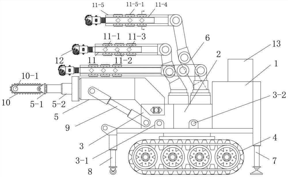
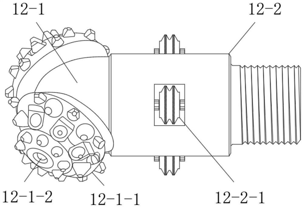
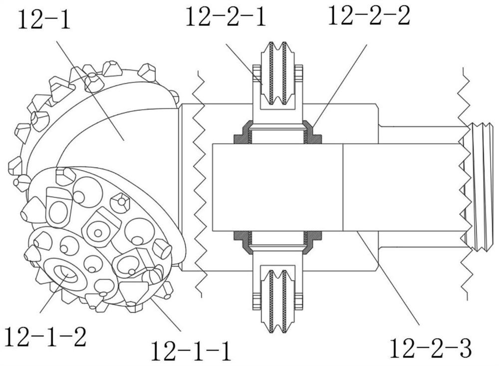
[0062] like Figures 1 to 12 As shown, the present invention also includes a self-diagnosing pre-cut hole dynamic pulling and shearing rock breaking device, including a control unit 1, an engine unit 2, a gas-liquid unit 3, a mobile unit 4, a cutting robotic arm 5, a drilling robotic arm 6, Fixed hydraulic support 7, movable hydraulic support 8 and stress and rock quality self-diagnosis system 13;

[0063] Described engine unit 2, gas-liquid unit 3 are provided with air pipe interface 3-1, water pipe interface 3-2, cutting robot arm 5, drilling robot arm 6;

[0064] The mobile unit 4 is powered by the engine unit 2 and controls the front, rear, left and right movement and steering movement;

[0065] like Figure 5 As shown, one end of the cutting robotic arm 5 is hinged on the moving unit 4, and the other end supports the moving unit 4 through a hydraulic support rod 9, and the hydraulic support rod 9 provides hydraulic oil through the gas-liquid unit 3; the cutting robotic ...

Embodiment 3

[0091] like figure 1 , 11 , 12, the difference between this embodiment and Embodiment 2 is that the drill rod 11 is provided with an inner sleeve 11-4 and an outer sleeve 11-5, and the inner sleeve 11-4 is fixed on the drill rod 11 On the outside, the outer sleeve 11-5 is evenly divided into four outer sleeve plates along the circumferential direction with the central axis of the drill pipe 11 as the center, and the outer sleeve plates are fixed to the inner sleeve by the hydraulic telescopic support rod 11-4-1 On the outside of 11-4, the outer side of the outer casing plate is provided with a tooth plate 11-5-1, the teeth on the tooth plate 11-5-1 are inclined along the retraction direction of the drill pipe, and when drilling, the outer casing plate shrinks and closes to the inner side. The sleeve, when the drill pipe is pulled out, controls a plurality of hydraulic telescopic support rods 11-4-1 to extend outward, thereby driving the outer sleeve plate to drive the tooth p...


PUM


Abstract

The invention relates to a self-diagnosis pre-cut hole dynamic tension shear rock breaking method and device, and the method comprises the following steps: a, grooving on a to-be-mined tunnel face along the periphery of the tunnel face to form a prefabricated seam, and forming a to-be-broken rock area on the tunnel face and in an area enclosed by the prefabricated seam; b, a plurality of vertical holes are formed in the range of the to-be-broken rock area in the direction perpendicular to the tunnel face, annular grooves with the diameter larger than that of the vertical holes are formed in the roots of the vertical holes in the radial direction of the vertical holes, or a plurality of transverse holes are formed in the roots of the vertical holes in the radial direction of the vertical holes; and c, outward pulling force in the axial direction of the vertical hole is applied to the side wall of the annular groove or the side wall of the transverse hole, and tensile shear and high stress combined rock breaking is achieved. According to the invention, traditional compression-shear rock breaking is changed into tension-shear and high-stress combined rock breaking, so that the rock breaking efficiency is effectively improved, the energy consumption is reduced, the high stress of the deep rock mass is utilized, the traditional non-continuous tunneling mode of blasting tunneling is improved, and the method is suitable for the deep high-stress rock mass.

Description

technical field [0001] The invention relates to a self-diagnostic pre-cut hole dynamic pulling and shearing rock breaking method and device. Background technique [0002] As the mining goes deep, the ore rock is hard, the stress is high, and the ore body is dispersed, which makes the hard rock cutting difficult, the continuous operation of drilling and blasting mining difficult, and the mining disturbance induces rock bursts and other disasters. It is difficult to move equipment and labor-intensive for workers to manually control, which restricts the safe and efficient recovery of rare metals. [0003] Deep resource exploitation is inseparable from rock drilling. In terms of rock drilling, domestic experts and scholars have carried out a lot of related research. For example, Huang-Kuilin of Southwest Petroleum University and other scholars aimed at PDC drill bits, rotating teeth and disc PDC in 360° On the basis of the drill bit, a rotary modular PDC bit is proposed, and th...

Claims


Application Information

Patent Timeline
Patent Type & Authority Applications(China)
IPC IPC(8): E21C25/66E21C25/18
CPCE21C25/66E21C25/18Y02P10/20
Inventor 董陇军王剑
Owner CENT SOUTH UNIV
Learn More