Sheep grouping device and control system thereof

A technology of guardrail and clamping mechanism, which is applied in the field of animal husbandry and can solve the problems of high labor intensity, high stress reaction of sheep, and unfavorable epidemic prevention.

Inactive Publication Date: 2019-03-26
INNER MONGOLIA AGRICULTURAL UNIVERSITY
View PDF11 Cites 12 Cited by
  • Summary
  • Abstract
  • Description
  • Claims
  • Application Information

AI Technical Summary

Problems solved by technology

For example, when weighing sheep, at present, it is mainly to fix the sheep by manual operation and then weigh them. The labor intensity is relatively high, and it needs to be in direct contact with the sheep, which is not conducive to epidemic prevention, and the stress response to the sheep is also great.

Method used


Image

  • Sheep grouping device and control system thereof
  • Sheep grouping device and control system thereof
  • Sheep grouping device and control system thereof

Examples


Embodiment 1

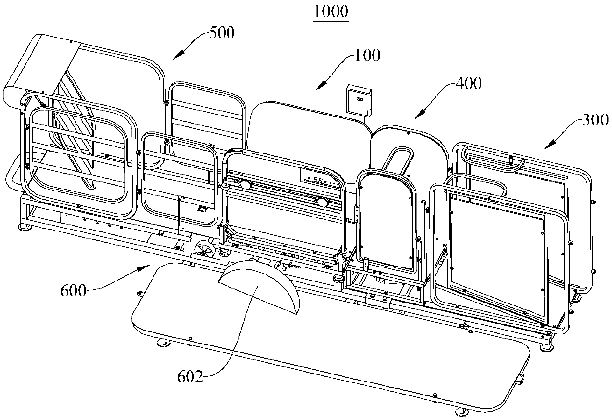
[0044] Please refer to figure 1 , figure 1 Shown is a schematic structural diagram of a sheep grouping device 1000 . This embodiment provides a sorting device 1000 for sheep, which is mainly used to assist management personnel in related management of sheep. Of course, in other embodiments, it can also be used to manage other livestock.

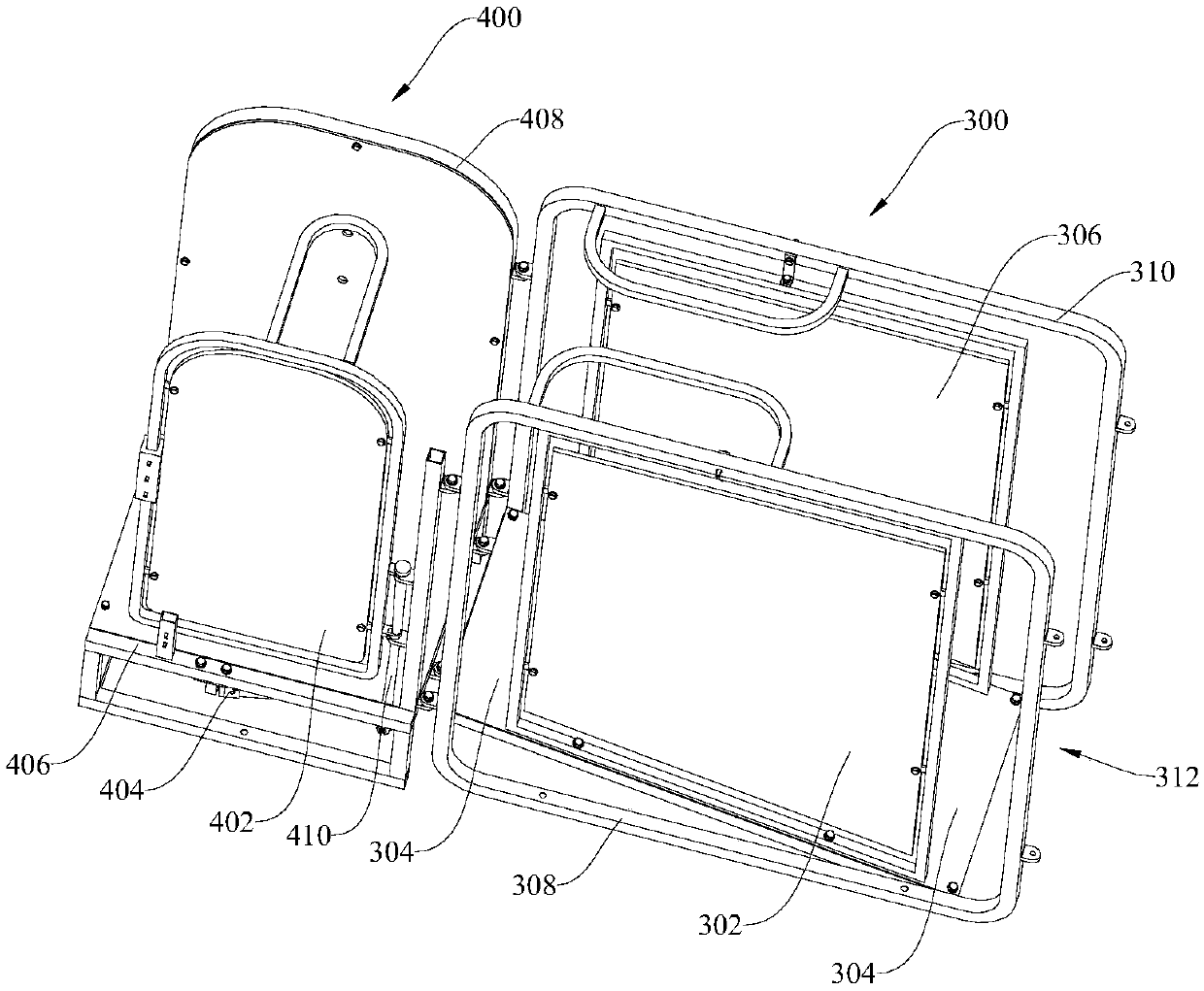
[0045] The sheep grouping device 1000 mainly includes a sheep clamping mechanism 100 , a detection mechanism 300 , a blocking mechanism 400 , a grouping mechanism 500 and a frame 600 . The detection mechanism 300 , the blocking mechanism 400 , the clamping mechanism 100 for sheep and the grouping mechanism 500 are all installed on the frame 600 . The detection mechanism 300, the barrier mechanism 400, the sheep clamping mechanism 100 and the grouping mechanism 500 are connected in sequence, and the sheep enter the detection mechanism 300, the barrier mechanism 400, the sheep clamping mechanism 100, and the grouping mechanism 500 in turn, a...

Embodiment 2

[0083] Please refer to Figure 10 , Figure 10 Shown is a control schematic diagram of the control system 2000 . This embodiment provides a control system 2000 for the above-mentioned sheep grouping device 1000 .

[0084] The control system 2000 mainly includes a PLC controller, a plurality of sensors, a man-machine interface (ie Figure 10 In the industrial control screen) and wireless transmission module. Sensors can be selected from ear tag readers, photoelectric switches, weight sensors, and object detectors according to specific needs. The number is not specifically limited. Multiple sensors can be installed at the same position for backup or to improve detection accuracy. Some sensors have been installed in corresponding positions in Embodiment 1, and object detectors for detecting the positions of sheep can also be installed in both the blocking mechanism 400 and the grouping mechanism 500 . The industrial control screen can move freely and record the physical chara...


PUM


Abstract

The invention provides a sheep grouping device and a control system thereof, and relates to the field of livestock breeding. The device mainly comprises a sheep clamping mechanism and a grouping mechanism. The sheep clamping mechanism comprises a base plate, a fixed plate and a clamping plate. The fixed plate and the clamping plate are both connected with the base plate and are oppositely arrangedat two sides of the base plate. The fixed plate, the base plate and the clamping plate together form a clamping space. The clamping plate and the base plate are rotatably connected to change the sizeof the clamping space. When sheep enters the clamping space, the clamping plate is rotated to fix the sheep, which is convenient for managers to dispose the sheep. The grouping mechanism is equippedwith a grouping channel which is communicated with the clamping space. The sheep enter the grouping mechanism under the guidance of the grouping channel. The grouping mechanism is provided with a first exit and a second exit, which are optionally in an open or close state such that the first exit and the second exit are connected with or disconnected with the grouping channel. When the first exitor the second exit is opened, the sheep enter different groups according to the different exits, thus completing the grouping.

Description

technical field [0001] The invention relates to the field of animal husbandry, in particular to a sheep grouping device and a control system thereof. Background technique [0002] With the rapid development of facility breeding, the number of various types of sheep breeding is increasing. For example, the number of sheep raised in captivity has increased dramatically, and the weighing, manicure and epidemic prevention of fattening sheep have become important tasks, which directly determine the cost of breeding and the development of pastures. For this reason, the sheep need to be clamped and fixed to complete other tasks such as weighing, epidemic prevention, turning and grouping. For example, when weighing sheep, at present, it is mainly to fix the sheep by manual operation and then weigh them. The labor intensity is relatively high, and it needs to be in direct contact with the sheep, which is not conducive to epidemic prevention, and the stress response to the sheep is a...

Claims


Application Information

Patent Timeline
Patent Type & Authority Applications(China)
IPC IPC(8): A01K1/00
CPCA01K1/00
Inventor 武佩王奎刘艳秋武晓玉宣传忠王昊毅刘忠舍朱晓波苏赫张海军马彦华
Owner INNER MONGOLIA AGRICULTURAL UNIVERSITY
Why Eureka
Try Eureka