
Chemical fiber wig forming device

A molding device and chemical fiber technology, applied in wigs, clothing, applications, etc., can solve problems such as increased production costs, low resource utilization, environmental pollution, etc., and achieve the effects of ensuring molding quality, high recycling rate, and reducing production costs.

Inactive Publication Date: 2019-03-26
禹州市靓佳工艺品有限公司
View PDF12 Cites 5 Cited by
  • Summary
  • Abstract
  • Description
  • Claims
  • Application Information

AI Technical Summary

Problems solved by technology

[0002] The wigs currently on the market are mainly chemical fiber wigs, which need to go through multiple processes to finally get the desired product. Curly wigs are one of the more common types of wigs in hair products. Curly wigs are shaped during the production process. It is an indispensable production link. The existing setting equipment often adopts heating and setting treatment. Uneven heating makes the setting effect poor, and the medicine flowing down from the wig cannot be processed in time, polluting the environment, and the resource utilization rate is low, which increases the production cost. Therefore, there is an urgent need to design a chemical fiber wig molding device with low production cost, easy operation, uniform heating, good styling effect, timely collection of medicaments flowing down from the wig, improved working environment, high recycling rate, and high production efficiency.

Method used


Image

  • Chemical fiber wig forming device
  • Chemical fiber wig forming device

Examples


Embodiment 1

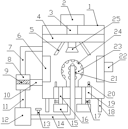
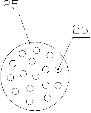
[0016] Such as Figure 1-2 As shown, a chemical fiber wig forming device includes a box body 1 and a hot air blower 12, the lower end of the box body 1 is provided with a leg 18, and the middle part of the upper end of the box body 1 is provided with a medicine storage tank 2. The medicine storage tank 2 is connected with the liquid distributor 4 through the medicine outlet pipe 3, the middle part of the lower end of the liquid distributor 4 is equipped with a nozzle 25, and the lower end of the nozzle 25 is provided with a liquid outlet 26, and the nozzle 25 is two Both sides are provided with a baffle A5, the baffle A5 is installed at the lower end of the liquid distributor 4, the middle part of the lower inner wall of the box body 1 is fixedly connected with a base 19, and the middle part of the upper end of the base 19 is provided with a wig head mold 23. The wig headform 23 is a hollow structure, and the wig headform 23 is provided with an air inlet 24, and one end of the...

Embodiment 2

[0019] Such as Figure 1-2As shown, a chemical fiber wig forming device includes a box body 1 and a hot air blower 12, the lower end of the box body 1 is provided with a leg 18, and the middle part of the upper end of the box body 1 is provided with a medicine storage tank 2. The medicine storage tank 2 is connected with the liquid distributor 4 through the medicine outlet pipe 3, the middle part of the lower end of the liquid distributor 4 is equipped with a nozzle 25, and the lower end of the nozzle 25 is provided with a liquid outlet 26, and the nozzle 25 is two Both sides are provided with a baffle A5, the baffle A5 is installed at the lower end of the liquid distributor 4, the middle part of the lower inner wall of the box body 1 is fixedly connected with a base 19, and the middle part of the upper end of the base 19 is provided with a wig head mold 23. The wig headform 23 is a hollow structure, and the wig headform 23 is provided with an air inlet 24, and one end of the ...


PUM


Abstract

The invention discloses a chemical fiber wig forming device. The device comprises a box body and an air heater, a medicine storage tank is arranged in the middle of the upper end of the box body, a liquid distribution device is connected to the medicine storage tank through a medicine outlet pipe, a sprayer is installed in the middle of the lower end of the liquid distribution device, and a base is connected to the middle of the inner wall of the lower side of the box body; a wig head mold is arranged in the middle of the upper end of the base, air inlets are formed in the wig head mold, an air inlet pipe is connected to one end of the air heater and stretches into the wig head mold, air outlets are formed in the air inlet pipe, and liquid discharge pipes are arranged at the left and rightsides of the base; the lower ends of the liquid discharge pipes stretch out of the box body, a collecting box is arranged below the liquid discharge pipes, heating lamps are arranged in the middles of the inner walls of the left and right sides of the box body, an air outlet pipe is connected to the left side of the upper portion of the box body, a dehumidifier is connected to the other end of the air outlet pipe, an air guide pipe is connected to the other end of the dehumidifier, and the other end of the air guide pipe is connected with the air heater. The chemical fiber wig forming devicehas the advantages that the production cost is low, heating is uniform, the sizing effect is good, the working environment is improved, the circular utilization rate is high, and the production efficiency is high.

Description

technical field [0001] The invention relates to the technical field of wig production equipment, in particular to a chemical fiber wig forming device. Background technique [0002] The wigs currently on the market are mainly chemical fiber wigs, which need to go through multiple processes to finally get the desired product. Curly wigs are one of the more common types of wigs in hair products. Curly wigs are shaped during the production process. It is an indispensable production link. The existing setting equipment often adopts heating and setting treatment. Uneven heating makes the setting effect poor, and the medicine flowing down from the wig cannot be processed in time, polluting the environment, and the resource utilization rate is low, which increases the production cost. Therefore, there is an urgent need to design a chemical fiber wig forming device with low production cost, easy operation, uniform heating, good styling effect, timely collection of medicament flowing ...

Claims


Application Information

Patent Timeline
IPC IPC(8): A41G3/00
CPCA41G3/0075
Inventor 张效聪
Owner 禹州市靓佳工艺品有限公司
Learn More