Gear bearing machine

A bending machine and gear technology, applied in the field of bending machines, can solve the problems of uneven heating, poor processing quality, and affecting the appearance of electric boilers, etc., and achieve the effect of fast bending and guaranteed bending effect

Inactive Publication Date: 2019-03-26
穆崇虎
View PDF7 Cites 1 Cited by
  • Summary
  • Abstract
  • Description
  • Claims
  • Application Information

AI Technical Summary

Problems solved by technology

Therefore, this work is still processed by workers using simple tools, and the processing speed is relatively slow. It takes two workers 20 to 30 minutes for a resistance wire of about 10 meters. The processing quality is poor, and the processed resistance wire is broken. There are big and small bends, which affect the appearance of the electric boiler and cause uneven heating.

Method used


Image

  • Gear bearing machine
  • Gear bearing machine
  • Gear bearing machine

Examples


Embodiment 1

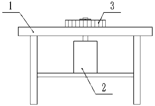
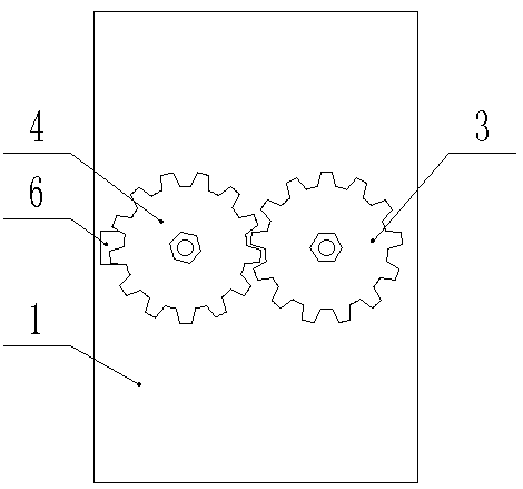
[0017] Such as Figure 1 to Figure 3 Shown: a gear bending machine, including: a platform 1, a motor 2, a driving gear 3, a driven gear 4 and a driven control assembly 5; a motor 2 is arranged under the platform 1, and the output shaft of the motor 2 is vertical It is arranged straight and the output shaft of the motor 2 passes through the platform 1 and can rotate relative to the platform 1. The output shaft of the motor 2 is fixed with a driving gear 3, and the platform 1 is provided with a chute 6. The driven gear 4 and the driving gear 3 meshes and the driven gear 4 can slide along the chute 6, a driven control assembly 5 for fastening the driven gear 4 is arranged between the driven gear 4 and the chute 6, and the driven gear 4 and the driving gear The distance between the 3 meshing teeth is max. 3mm.

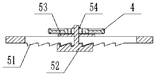
[0018] The driven control assembly 5 includes: a fixed tooth 51, a driven tooth 52, a gasket 53 and a fastening nut 54; The fixed tooth 51 is a plurality of protruding t...

Embodiment 2

[0021] Such as figure 1 , figure 2 , Figure 4 and Figure 5 Shown: a gear bending machine, including: a platform 1, a motor 2, a driving gear 3, a driven gear 4 and a driven control assembly 5; a motor 2 is arranged under the platform 1, and the output shaft of the motor 2 is vertical It is arranged straight and the output shaft of the motor 2 passes through the platform 1 and can rotate relative to the platform 1. The output shaft of the motor 2 is fixed with a driving gear 3, and the platform 1 is provided with a chute 6. The driven gear 4 and the driving gear 3 meshes and the driven gear 4 can slide along the chute 6, a driven control assembly 5 for fastening the driven gear 4 is arranged between the driven gear 4 and the chute 6, and the driven gear 4 and the driving gear The distance between the 3 meshing teeth is max. 3mm.

[0022] The shape and structure of the driving gear 3 and the driven gear 4 are consistent, and the driving gear 3 includes: a tooth bracket, a...


PUM


Abstract

The invention discloses a gear bending machine, and belongs to the field of bending machines. A bending machine special for bending of resistance wires of an electric heating boiler is provided, and the bending machine can adjust the bending magnitude according to the machined resistance wires. According to the technical scheme, the gear bending machine comprises a platform, a motor, a driving gear, a driven gear and a driven control assembly; the motor is arranged below the platform, an output shaft of the motor is vertically arranged, the output shaft of the motor penetrates through the platform and can rotate relative to the platform, the driving gear is fixed to the output shaft of the motor, a sliding groove is formed in the platform, the driving gear and the driven gear are engaged,the driven gear can slide along the sliding groove, a driven control assembly fastening the driven gear is arranged between the driven gear and the sliding groove, and the maximum distance between engaged teeth of the driving gear and the driven gear is 3 mm.

Description

technical field [0001] The invention relates to a gear bending machine, which belongs to the field of bending machines. Background technique [0002] With the gradual promotion of the national coal-to-electricity policy, many households have begun to use electric boilers. The resistance wire of electric boilers is a kind of lath-shaped metal with several bends. At present, there is no special mechanical device that can bend the resistance wire from a long straight state to a zigzag state. Therefore, this work is still processed by workers using simple tools, and the processing speed is relatively slow. It takes two workers 20 to 30 minutes for a resistance wire of about 10 meters. The processing quality is poor, and the processed resistance wire is broken. There are large and small bends, which affect the appearance of the electric boiler and cause uneven heating. Contents of the invention [0003] In order to overcome the above technical problems, the present invention ...

Claims


Application Information

Patent Timeline
Patent Type & Authority Applications(China)
IPC IPC(8): B21D11/07B21D11/22
CPCB21D11/07B21D11/22
Inventor 穆崇虎
Owner 穆崇虎
Why Eureka
Try Eureka