An oil pipe moving device

A mobile device, oil pipe technology, applied in transportation and packaging, ship construction, ship design, etc., can solve problems such as difficulty, heavy oil pipe weight, frictional contact, etc.

Active Publication Date: 2019-12-06
WUHAN MARINE MACHINERY PLANT
View PDF9 Cites 0 Cited by
  • Summary
  • Abstract
  • Description
  • Claims
  • Application Information

AI Technical Summary

Problems solved by technology

Due to the heavy weight of the oil pipe and the frictional contact with the inner hole of the intermediate shaft, it is difficult and time-consuming to manually move the oil pipe at present.

Method used


Image

  • An oil pipe moving device
  • An oil pipe moving device
  • An oil pipe moving device

Examples


Embodiment Construction

[0030] In order to make the object, technical solution and advantages of the present invention clearer, the implementation manner of the present invention will be further described in detail below in conjunction with the accompanying drawings.

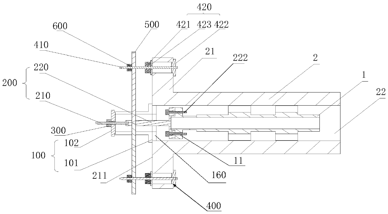
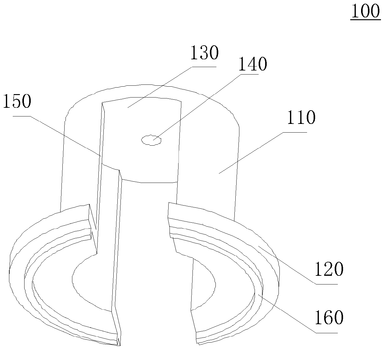
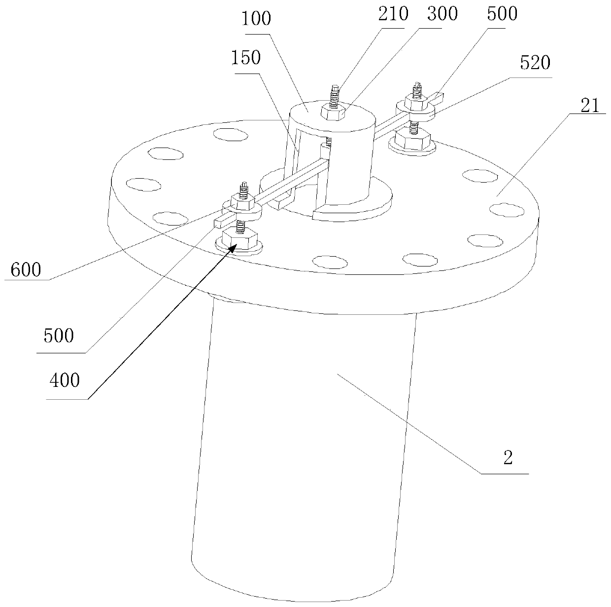
[0031] figure 1 It is a cross-sectional view of an oil pipe moving device provided by an embodiment of the present invention. Such as figure 1 As shown, the oil pipe 1 is passed through the cavity 22 of the intermediate shaft 2, the end of the oil pipe 1 is provided with an oil pipe flange 11, and the oil pipe flange 11 can be used to connect the flanges of other oil pipes, and the end of the intermediate shaft 2 is provided with There is an intermediate shaft flange 21 , which can be used to connect flanges of other intermediate shafts or adjusting rings, and the intermediate shaft flange 21 includes a flange end face 211 . Such as figure 1 As shown, the oil pipe moving device includes a support base 100 , a pull-out assembly 200 ,...


PUM


Abstract

The invention discloses an oil pipe moving device, and belongs to the field of mounting machinery. The oil pipe moving device comprises a supporting base, a pull-out assembly, a pull-out nut, a press-in assembly, a press-in connecting rod and a press-in nut; one end of the pull-out assembly is connected with a flange of the oil pipe, and a pull-out lead screw is arranged at the other end of the pull-out assembly and penetrates through a through hole of the supporting base. The pull-out nut is arranged on the part, extending out of the second end face, of the pull-out lead screw in a sleeving manner; one end of the press-in assembly is connected with an intermediate shaft flange, and a press-in lead screw is arranged at the other end of the press-in assembly; one end of the press-in connecting rod is arranged on the press-in lead screw through a positioning hole in a sleeving manner, and the other end of the press-in connecting rod is detachably connected with the pull-out assembly; thepress-in nut sleeves the press-in lead screw, and the press-in connecting rod is located between the press-in nut and a flange end face. In the using process, an oil pipe is moved by rotating the pull-out nut and the press-in nut through a spanner.

Description

technical field [0001] The invention relates to the field of installation machinery, in particular to an oil pipe moving device. Background technique [0002] The controllable pitch propeller device is a ship power propulsion device, which is widely used in shipping ships. A controllable pitch propeller device generally includes a hub blade assembly, a shafting, an oil pipe assembly and an oil distributor assembly. The hub blade assembly is located at the stern of the ship, the oil distributor assembly is generally located in the middle of the ship, the shafting is located between the hub blade assembly and the oil distributor assembly, and the oil pipe assembly is located inside the shafting. For controllable pitch propeller devices with a long distance between the oil distributor and the propeller hub and blade assembly, the shaft system generally includes multiple sections of intermediate shafts and an adjustment ring, and a section of oil pipe is arranged in each sectio...

Claims


Application Information

Patent Timeline
Patent Type & Authority Patents(China)
IPC IPC(8): B63B9/00B63H3/00
CPCB63B71/00B63H3/00
Inventor 赵章献魏雪乔维桑雪梅王帅
Owner WUHAN MARINE MACHINERY PLANT
Why Eureka
Try Eureka