a wine beater

A technology for a wine beater and a main body, applied in the field of wine beaters, can solve the problems of limited use occasions, low controllable precision of gas output efficiency, different speed of beverage filling, etc., achieves strong adaptability and versatility, and improves controllable precision. , easy to use effect

Active Publication Date: 2020-05-05
TALOS TECH CORP
View PDF14 Cites 0 Cited by
  • Summary
  • Abstract
  • Description
  • Claims
  • Application Information

AI Technical Summary

Problems solved by technology

In addition, depending on the occasion of use and the number of people drinking, the speed of the drink will also be different.
Therefore, because the function of this wine beater is comparatively single, it is impossible to control the gas outlet efficiency, and the application occasions are comparatively limited.
[0004] Although the wine beater can be additionally equipped with a pressure reducing valve to realize the function of adjusting the outlet pressure, the traditional pressure reducing valve, whether it is a diaphragm type or a plunger type, will not release the gas after decompression. Flow is also not adjustable
For example, the application number disclosed in the Chinese patent literature is 201420296406.4, and the patent name is a diaphragm of a carbon dioxide pressure reducing valve to make the pressure reducing valve structure. Another example is the US patent with the publication number US2006 / 0169328A1. The valve structure and the outlet flow of the gas after decompression are also unadjustable
Therefore, even if the existing wine beater is used in conjunction with the pressure reducing valve, only the pressure of the gas outlet can be adjusted, resulting in low controllable accuracy of the gas outlet efficiency

Method used


Image

  • a wine beater
  • a wine beater
  • a wine beater

Examples


Embodiment 1

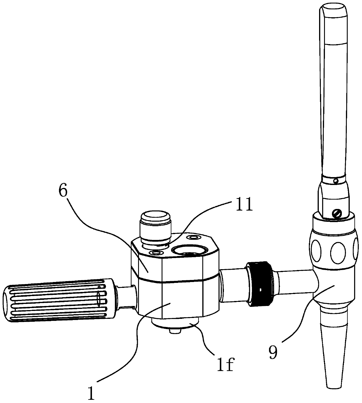
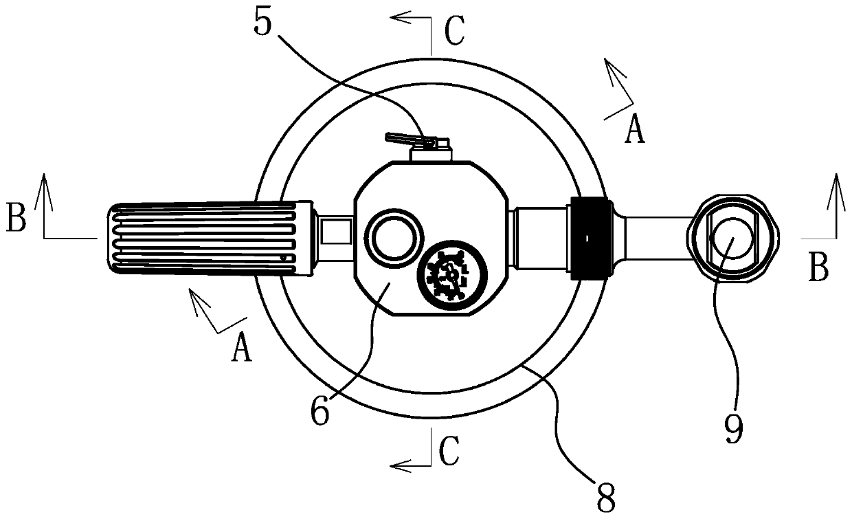
[0035] Such as figure 1 with figure 2 As shown, the wine beater includes a main body 1, the bottom of the main body 1 has an insertion part 1f for inserting on the barrel mouth of the wine barrel 8, and the main body 1 is connected with a tap 9 for dispensing wine.

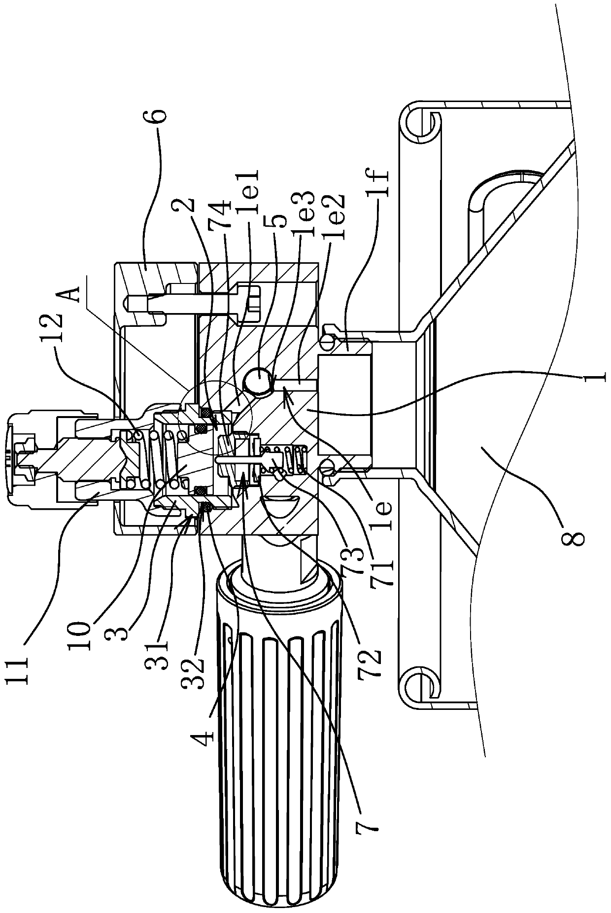
[0036] combine image 3 , Figure 4 with Figure 5 As shown, the wine beater also includes a decompression chamber 2, an adjustment sleeve 3, an air intake passage 1d, and an air outlet passage 1e for delivering the gas in the decompression chamber 2 to the barrel 8. The main body 1 is also connected with a useful As for the wine guide tube 13 leading out the wine, the main body 1 is also provided with a liquid outlet channel 1g, and the wine in the barrel 8 can flow to the faucet 9 through the wine guide tube 13 and the liquid outlet channel 1g in turn. An installation groove 1a is opened on the outer wall of the main body 1, and the decompression chamber 2 is located in the installation groove 1a. Such as ...


PUM


Abstract

The invention provides a wine dispenser, and belongs to the technical field of wine distribution equipment. The problem that the air exhaust efficiency controlling efficiency of a wine dispenser in the prior art is low is solved. The wine dispenser comprises a main body, a pressure reduction cavity and an air inlet structure for supplying air to the pressure reduction cavity. The outer wall of themain body is provided with an installation groove, and the pressure reduction cavity is located in the installation groove. The wine dispenser further comprises an adjusting sleeve, the side wall ofthe installation groove is provided with an air outlet communicating with the pressure reduction cavity, the inner end of the adjusting sleeve is inserted into the installation groove and is in threaded connection with the side wall of the installation groove, and the inner end of the adjusting sleeve can partially block the air outlet. Air exhaust flow can be adjusted, and the wine dispenser hasthe advantage of being high in air exhaust efficiency controlling precision.

Description

technical field [0001] The invention belongs to the technical field of wine dispensing equipment, and relates to a wine whisk. Background technique [0002] As fresh beer is accepted by more and more people in China, beer beverage equipment has also been widely used. However, some commercial beer drinking equipment is bulky and expensive, and is not suitable for some household occasions or outdoor occasions, so some portable beer drinking equipment has been derived. The portable wine brewing equipment is a highly integrated and small component. When in use, it only needs to be installed on the wine barrel, and then connected to the air source and the faucet to realize the wine. [0003] For example, the Chinese patent literature discloses a portable wine beer (application number: 201520154522.7), which includes an air intake mechanism, a liquid outlet mechanism for discharging the beer in the beer keg, and a cover for connecting with the beer keg. The liquid outlet mechani...

Claims


Application Information

Patent Timeline
Patent Type & Authority Patents(China)
IPC IPC(8): B65D25/42
CPCB65D25/42
Inventor 邱迪清
Owner TALOS TECH CORP
Why Eureka
Try Eureka