
Polarizer and display device provided with polarizer

A technology for display devices and polarizers, applied in optics, optical elements, polarizing elements, etc., can solve problems affecting optical quality, cracks in optical compensation films, and different thermal expansion and contraction coefficients, etc.

Active Publication Date: 2019-03-26
AU OPTRONICS CORP
View PDF10 Cites 3 Cited by
  • Summary
  • Abstract
  • Description
  • Claims
  • Application Information

AI Technical Summary

Problems solved by technology

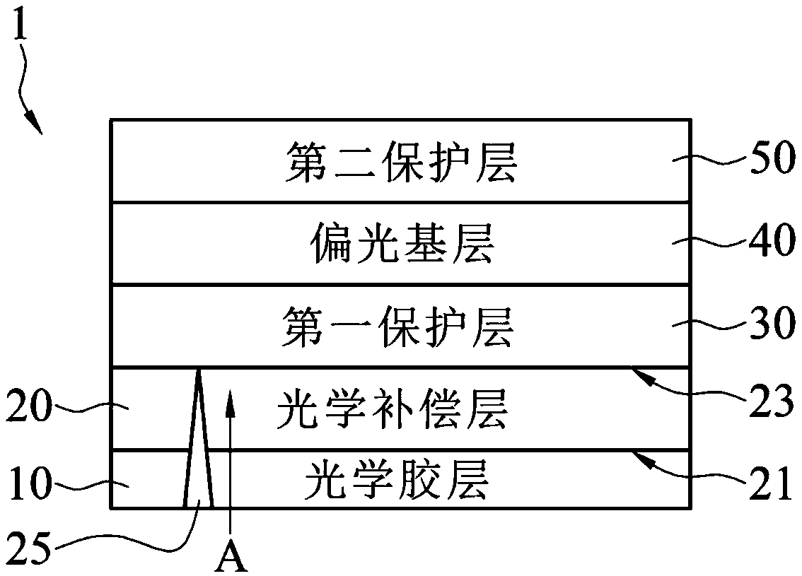
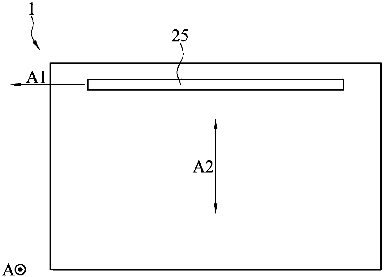
[0003] Optical compensation film, also known as phase retardation film, can be attached to the display panel through optical glue, but it may be due to the different thermal expansion and contraction coefficients between the optical compensation film and the optical glue, or the stretching during the process Stress, which causes the optical compensation film to produce cracks at the stretching or cutting of the edge of the optical compensation film due to stress concentration
When used for a long time, the cracks may continue to expand along the stretching direction of the optical compensation layer, and extend to the area of ​​the optical compensation film that is vertically projected on the display area of ​​the display, thereby affecting the overall optical quality

Method used


Image

  • Polarizer and display device provided with polarizer
  • Polarizer and display device provided with polarizer
  • Polarizer and display device provided with polarizer

Examples


Embodiment Construction

[0037] Below in conjunction with accompanying drawing, structural principle and working principle of the present invention are specifically described:

[0038] In the drawings, the thickness of layers, films, panels, regions, etc., are exaggerated for clarity. Throughout the specification, the same reference numerals denote the same elements. It will be understood that when an element such as a layer, film, region, or substrate is referred to as being "on," "connected to," or "in contact with" another element, it can be directly on, on, or in contact with the other element. An element may be connected to, or in direct contact with, another element, or intervening elements may also be present. In contrast, when an element is referred to as being "directly on," "directly connected to," or "directly contacting" another element, there are no intervening elements present.

[0039] It should be understood that although the terms "first", "second", "third" etc. may be used herein t...


PUM


Abstract

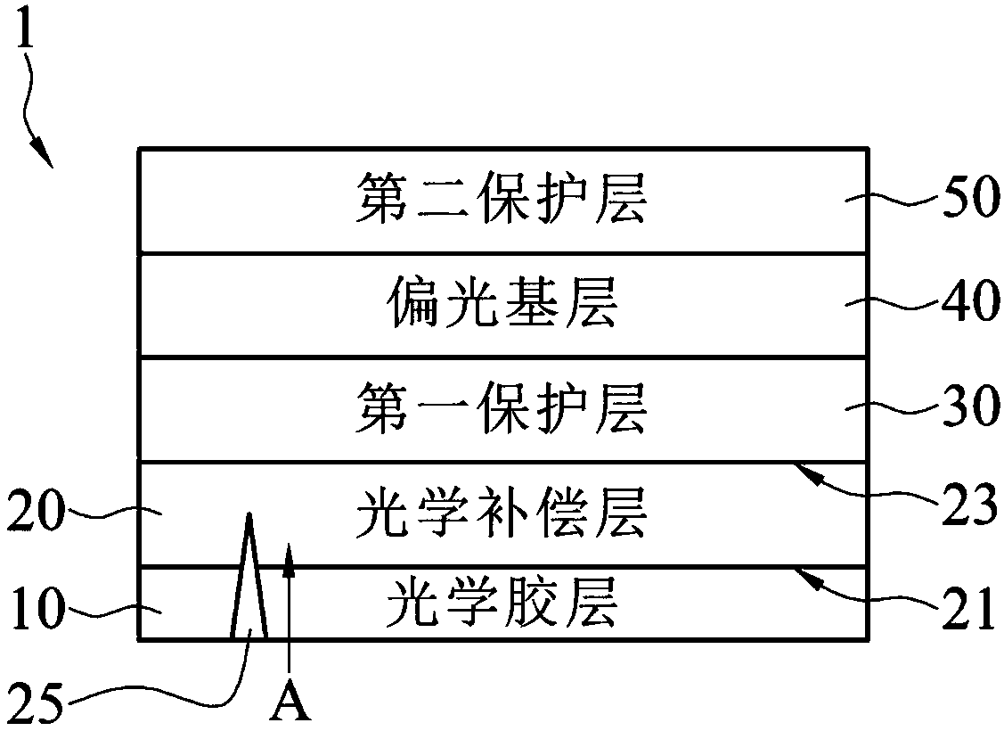
A polarizer and a display device provided with the polarizer are disclosed. The polarizer includes an optical adhesive layer, an optical compensation layer, a first protective layer, a polarizing baselayer and a second protective layer. The optical compensation layer is located on the optical adhesive layer. The optical compensation layer has a first surface and a second surface relative to the first surface. The optical compensation layer has at least one crack arresting groove, which extends from the first surface to the second surface, and the extension direction of the crack arresting groove is perpendicular to the tensile direction of the optical compensation layer. The first protective layer is on the optical compensation layer, the polarizing base layer is on the first protective layer, and the second protective layer is on the polarizing base layer. In order to maintain the optical characteristics of the display device, a crack stop groove is formed in the optical compensationlayer, which can prevent the crack existing in the stretching or cutting part of the edge of the optical compensation layer from extending to the position projected vertically on the display area ofthe display device.

Description

technical field [0001] The invention relates to the field of displays, in particular to a polarizer and a display device using the polarizer. Background technique [0002] A polarizer can be used in the display to deflect the outgoing light in a specific direction. The polarizer is usually a multi-layer structure, and an optical compensation film is provided in the multi-layer to compensate for phase delay. [0003] Optical compensation film, also known as phase retardation film, can be attached to the display panel through optical glue, but it may be due to the different thermal expansion and contraction coefficients between the optical compensation film and the optical glue, or the stretching during the process Stress causes the optical compensation film to produce cracks at the stretching or cutting part of the edge of the optical compensation film due to stress concentration. When used for a long time, the cracks may continue to expand along the stretching direction of...

Claims


Application Information

Patent Timeline
IPC IPC(8): G02B5/30
CPCG02B5/30G02B5/3033G02B5/3041G02B5/305
Inventor 邱盛垣李俊右邵明良古清芳
Owner AU OPTRONICS CORP
Learn More